This project is yet another test equipment that can be extremely handy to any electronic hobbyist, and building this unit can be a lot of fun.
A capacitance meter is a very useful test equipment as it allows the user to check a desired capacitor and confirm its relaibility.
Ordinary or standard digital meters mostly do not have a capacitance meter facilty, and therefore an electronic enthusiast has to depend on costly meters to get this facility.
The circuit discussed in the following article, explains an advanced yet cheap 3-digit LED capacitance meter, which provides a reasonably accurate measurement for a range of capacitors that are commonly used in all contemporary electronic circuits.
Capacitance Ranges
The proposed capacitance meter circuit design provides a 3 digit LED display, and it measures the values with five ranges, as indicated below:
Range#1 = 0 to 9.99nF
Range#2 = 0 to 99.9nF
Range#3 = 0 to 999nF
Range#4 = 0 to 9.99µF
Range#5 = 0 to 99.99µF
The above ranges include most of the standard values, however the design is unable to determine extremely low values of a few picofarads, or high value electrolytic capacitors.
Practically this limitation may not be too much concern since extremely low value capacitors are seldom used in present day electronic circuits, while the large capacitors could be tested utilizing a couple of series connected capacitors, as is going to be described in-depth later on in the following paragraphs.
How it Works
An overflow warning LED is incorporated in order that inaccurate readings are prevented in case an inappropriate range is chosen. The device is driven through a 9 volt battery, and hence it is absolutely portable.
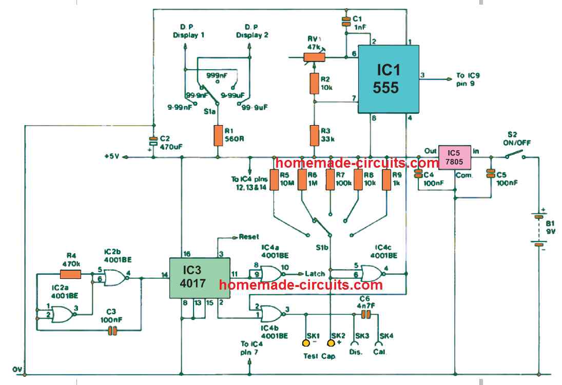
Figure 2 exhibits the circuit diagram for the clock oscillator, an low Hz oscillator, logic controller, and monostable multivibrator stages of the LED capacitance meter circuit.

The counter/driver and overflow circuit stages are shown in the next Figure above.
Looking at the Figure 2, IC5 is a 5 volt fixed voltage regulator that provides a nicely regulated 5 volt output from the 9 volt battery source. The entire circuit uses this regulated 5 volt power for the functioning.
The battery should be of a high mAh rating since the current usage of the circuit is fairly large at around 85 mA. The current consumption could go beyond 100 mA whenever most of the digits of the 3-display are being illuminated for the displaying.
The low frequency oscillator is built around the IC2a and IC2b that are CMOS NOR gates. Nevertheless, in this particular circuit these ICs are connected as basic inverters and applied through normal CMOS astable setup.
Observe that the working frequency of the oscillator stage is a lot bigger compared to the frequency with which the readings are provided, because this oscillator has to generate 10 output cycles for enabling the completion of a single reading cycle.
IC3 and IC4a are configured as the control logic stage. IC3 which is a CMOS 4017 decoder/counter, includes 10 outputs ('0' to '9'). Each of these outputs go high, in succession, for every single consecutive input clock cycle. In this particular design output '0' supplies the reset clock to the counters.
Output '1' subsequently becomes high and toggles the monostable which produces the gate pulse for the clock/counter circuit. Outputs '2' to '8' are unconnected, and the time interval throughout which these 2 outputs turn high enables a little bit of time so that the the gate pulse can complete and to allow the counting to become over.
Output '9' supplies the logic signal which latches the new reading over the LED display, however this logic needs to a negative one. This is accomplished with IC4a which inverts the signal from output 9 so that it translates into a appropriate pulse.
The monostable multivibrator is a a standard CMOS version using a couple of 2 input NOR gates (IC4b and IC4c). Despite being a simple monostable design, it offers features that make it perfectly worthy of the current application.
This is a non-retriggerable form, and as a result provides an output pulse which is smaller than the trigger pulse generated from IC3. This function is actually critical, because when a retriggerable type is used the least display reading could be fairly high.
The proposed design's self capacitance is pretty minimal, which is essential since a substantial degree of local capacitance could disturb the circuit linear attribute, resulting in a huge lowest display reading.
While using, the prototype display could be seen with reading '000' across all 5 ranges when there's no capacitor connected across testing slots.
Resistors R5 to R9 function as range selection resistors. When you decrease the timing resistance across decade steps, the timing capacitance required for a particular reading gets increased in the decade increments.
If we consider that the range resistors are rated with tolerance of at least 1%, this set up can be expected to deliver reliable readings. This means, it may not be necessary for each range to be calibrated separately.
R1 and S1a are wired to run the decimal point segment on the correct LED display, except for the Range 3 (999nF) in which a decimal point indication is not necessary. The clock oscillator is actually a common 555 astable configuration.
Pot RV1 is used as the clock frequency controller, for calibrating this LED capacitance meter. The monostable output is used for controlling the pin 4 of IC 1, and the clock oscillator will be activated only while the gate period is available. This function eliminates the demand for a independent signal gate.
Now checking the Figure 3, we find that the counter circuit is wired using 3 CMOS 4011 ICs. These are actually not recognized from the ideal CMOS logic family, nevertheless these are extremely flexible elements that are worthy of frequent consumption.
These are actually configured as up/down counters having individual clock inputs and carry/borrow outputs. As can be understood, the potential to use in the down counter mode is meaningless here, the down clock input is therefore hooked with the negative supply line.
The three counters are connected in sequence to allow a conventional 3 digit display. Here, IC9 is wired to generate the least significant digit and IC7 enables the most significant digit. The 4011 includes a decade counter, a seven segment decoder, and a latch/display driver stages.
Every single IC could for that reason substitute a typical 3 chip TTL style counter/driver/latch option. The outputs have enough power to directly illuminate any appropriate common cathode seven segment LED display.
Despite of a low voltage supply of 5 volts it is recommended to drive every single LED display segment through a current limiting resistor so that the current consumption of the entire caapcitance meter unit can be kept below an acceptable level.
The IC7's 'carry' output is applied to the IC6 clock input, that is a dual D type divide by two flip/flop. However in this particular circuit just one portion of the IC is implemented. The IC6 output will switch state only when there's an overload. This implies, if the overload is significantly high will result in many output cycles from IC7.
Directly powering the LED indicator LED1 through IC6 could be quite inappropriate, because this output can be momentary and the LED may possibly be able to generate just a couple of short illuminations that could be easily go unnoticed.
In order to avoid this situation the IC7 output is used to drive a basic set/reset bistable circuit created by wiring a pair of normally empty gates of IC2, and subsequently the latch switches the LED indicator LED1. The two IC6 and the latch are reset by IC3 in order that the overflow circuit commences from scratch whenever a new test reading is implemented.
How to Build
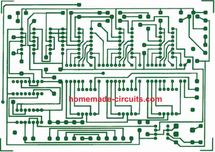
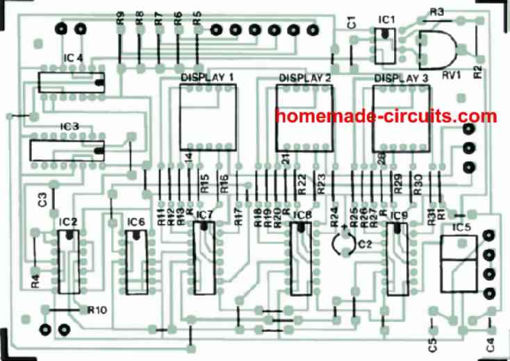
Constructing this 3 digit capacitance meter circuit is just about assembling all the parts correctly over the below given PCB layout.
Remember that the IC are all CMOS types and therefore sensitive to static electricity from your hand. To avoid damage through static electricity use of IC sockets are recommended. Hold the ICs on their body and push into the sockets, without touching the pins in the process.
Calibration
Before you begin calibrating this finalized 3 digit LED capacitance meter circuit, it may be important to employ a capacitor with a tight tolerance and a magnitude which provides approximately 50 to 100% of the full scale range of the meter.
Let's imagine that C6 has been incorporated in the unit and is applied to calibrate the meter. Now, adjust the device to range#1 (9.99 nF full scale) and insert a direct link across SK2 and SK4.
Next, very gently adjust RV1 to visualize the appropriate reading of 4.7nF on the display. Once this is done, you may find the unit showing the correspondingly correct readings across a range of capacitors.
However please do not anticipate the readings to be exactly accurate. The 3 digit capacitance meter on its own is fairly precise, although, as discussed earlier, it will practically be accompanied with some minor discrepancies for sure.
Why 3 LED Displays are Used
Many capacitors tend to have rather large tolerances, although handful of varieties might include an accuracy rate of higher than 10%. Practically speaking, the introduction of the 3rd LED display digit may not be justified with respect to the expected precision, nonetheless it is advantageous due to the fact that it efficiently expands the lowest capacitance that the device is able to read through a complete decade.
Testing Old Capacitors
In case an old capacitor is tested with this equipment, you could possibly see that the digital reading on the display is gradually rising. This may not necessarily signify a faulty capacitor, rather this may be simply as a result of warmth of our fingers causing the capacitor value to go up marginally. While inserting a capacitor in the SKI and SK2 slots, make sure to hold the capacitor by its body, and not the leads.
Testing Overrange High Value Capacitors
High value capacitors which are not within the range of this LED capacitance meter, could be examined by connecting the high value capacitor in series with a lower value capacitor, and then testing the total series capacitance of the two units.
Let's say , we want to examine a capacitor having a 470 µF value printed on it. This may be implemented by attaching it in series with 100µF capacitor. Then the value of the capacitor 470 µF could be verified using the following formula:
(C1 x C2)/(C1 + C2) = 82.5 µF
The 82.5 µF will confirm that the 470 µF is fine with its value. But suppose, if the meter shows some other reading such as 80 µF, that would mean the 470 µF is not OK, since its actual value then would be:
(X x 100)/(X + 100) = 80
100X / X + 100 = 80
100X = 80X + 8000
100X - 80X = 8000
X = 400 µF
The result indicates that the tested 470µF capacitor's health may not be very good
The two additional sockets (SK3 and SK4) and capacitor C6 can be seen in the diagram. The intention of SK3 is to make it easy for test elements to be discharged by touching across SK1 and SK3 before plugin them across SKI and SK2 for the measurement.
This is applicable only to those capacitors that may have the tendency to store some residual charge when removed from a circuit just before testing. High value and high voltage type capacitors are the ones that may be susceptible to this issue.
However, in serious conditions capacitors may need to be gently discharged via a bleed resistor prior to taking out them out from a circuit. The reason for including SK3 is to allow the capacitor under test to be discharged by connecting across SK1 and SK3 before testing them across SKI and SK2 for the measurement.
C6 is a handy, ready to use, sample capacitor for quick calibration purpose. In case a capacitor under test shows a some flawed reading, then it could be essential to switch to range 1, and putting a jumper link across SK2 to SK4 so that C6 gets connected as the test capacitor. Next, you may want to checking ensuring that a legitimate value of 47nF is indicated over the displays.
However, there's one thing that needs to be understood: The meter by itself is fairly accurate within a few % plus/minus, apart from capacitor values almost identical to the calibration value. An additional issue is that the capacitor readings may be dependent on temperature and a few external parameters. In case a capacitance reading shows a slight error in excess to its tolerance value, this most likely indicates that the part is absolutely OK, and is no way defective.
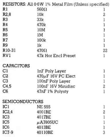
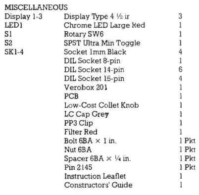
Parts List
can this circuit will be modified to check 2000uf
I think that may be possible, by cascading more number of display driver stages.
Hocam devremiz kapasite metre ile ohm metremidir teşekkürler.