In this post I will show how to construct a modified sine wave inverter using Arduino. We will explore the methodology of the proposed sine wave inverter and finally, we will take a look at simulated output of this inverter.
By
Difference Between Squarewave and Modified Squarewave Inverter
Inverters saved us from short term power cuts at home, industries and emergency rooms. The quality of power of delivered by inverters vary depending on what type of inverter is used. Inverters are classified into three types: square wave, modified sine wave and pure sine wave inverters.
A square wave inverter has poor quality output and contains lot of harmonic noise which may not suitable for many electronic gadgets. Its wave form goes up and down peak. But, resistive loads such as incandescent bulbs, heater and some devices which employees SMPS don’t exhibit problem with square wave inverters.
A modified sine wave or modified square wave to be precise can run most of the electronic gadgets without much issue.
The wave form goes peak up and come down to zero volt and stays for some interval and goes negative peak and come back to zero volt and cycle repeats. It has harmonic noise but not as bad as square wave and can be filtered easily. This design is used in most of the inexpensive inverters.
A pure sine wave inverter has most sophisticated design and expensive one. It can run all electronic devices including inductive loads such as motors which have problems in operating with other mentioned designs. It has no harmonics and wave form is smooth sinusoidal.
By now you know the basic difference between sine, modified sine and square wave inverters.
In this project we are constructing an inverter which can deliver output equivalent to sine wave inverter.
The circuit can be understood better by given block diagram below:
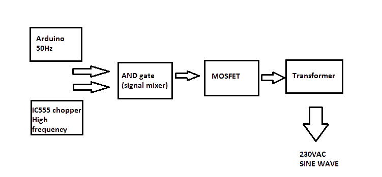
The proposed design consists of an Arduino which generates 50Hz constant square wave. An IC 555 chopper circuit generates high frequency pulse.
The actual chopping of these two signals is done by IC 7408, which is AND gate. The mixed signal is fed to gate of MOSFET. The frequency of IC 555 can be varied for adjusting the output voltage by tuning the variable resistor.
Circuit Diagram:
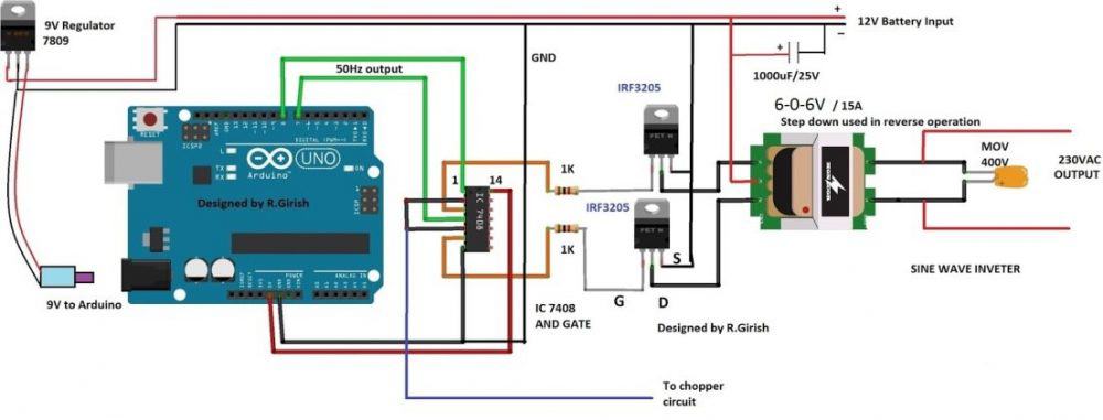
The constant 50Hz square wave is generated across pin #7 and pin #8 of Arduino. This flip-flop signal is fed to pin #1 and pin #4 of IC 7408. These two pins are of two different AND gates.
The high frequency chopping signal is fed to pin #2 and #5. The AND gate allows only when two inputs are high, since the Arduino frequency output is lower and IC555 higher, we get chopped signal at the corresponding gate output.
The chopped output is fed to MOSFET with a current limiting resistor for limiting the gate capacitor charging rate. A 12V 15A or higher rated transformer can be used if you need higher wattage output.
A 400V metal oxide varistor is utilized across the output for suppressing initial high voltage surge while turning on the inverter; it could be several hundreds of volts in magnitude.
A 9V regulator is used for arduino as constant voltage source. A 1000uF or higher capacitance can be used at battery input for smooth starting and to protect the inverter from sudden voltage fluctuations.
Chopper circuit:
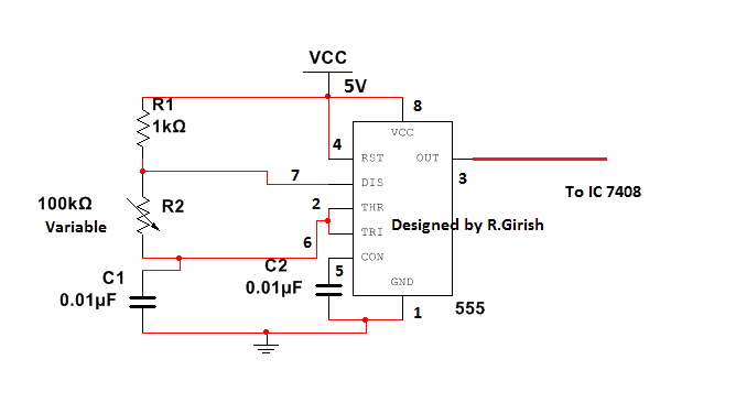
The chopper circuit is simple variable frequency generator, and the circuit is self-explanatory.
Now let’s see how well the frequency from Arduino is chopped by high frequency generator circuit to achieve sine wave equivalent.
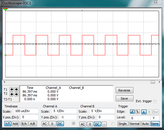
The above simulation describes the output from arduino. It’s a simple and stable 50Hz signal.
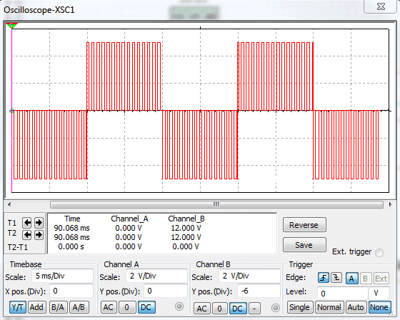
The above simulation shows the wave form after chopping the constant 50Hz signal. The width of the chopping ratio can be adjusted by tuning the variable resistor and which also determine the output voltage.
The above chopped signal may not look like sine wave. A real sine wave inverter’s chopped wave form increase and decrease exponentially across x-axis. But begin a simple design the chopping frequency stay constant and good enough to run most of electronic gadgets.
Program for Arduino:
//-------------Program developed by R.Girish-----------//

int out1 = 8;

int out2 = 7;

void setup()

{

pinMode(out1,OUTPUT);

pinMode(out2,OUTPUT);

}

void loop()

{

digitalWrite(out2,LOW);

digitalWrite(out1,HIGH);

delay(10);

digitalWrite(out1,LOW);

digitalWrite(out2,HIGH);

delay(10);

}

//-------------Program developed by R.Girish----------//
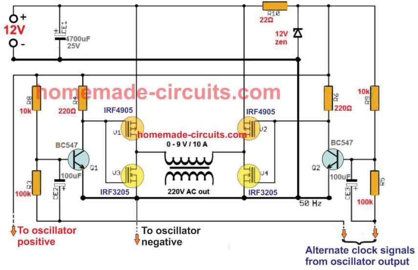
For a Full Bridge version you can refer to this design: https://www.homemade-circuits.com/arduino-full-bridge-h-bridge-sinewave-inverter-circuit/


Questions & Answers
Hlo sir my name abhishek kumar i am the polytechnic Electrical final sem student i want that this project will make what do you think this circuit will work perfectly for this project?
Hello Abhishek, the author of this article has tested the circuit, so as far as I know it should work.
Excuse me sir can tell me about that circuit how much load it take
Abhishek, the power will depend on the wattage of the transformer and the battery. You can select them as per your requirement. You can build a similar circuit without Arduino, which is much easier and efficient, as presented here:
https://www.homemade-circuits.com/modified-sine-wave-inverter-circuit-2/
Hlo sir i buy all components for that inverter but tranformer as diagram same rating 6-0-6 volt 15 amp is not available can I replace it with a low power amp and 12-0-12 volt transformer?
Hello Abhishek, If you use 12-0-12V transformer then the output could be less than 200 V even 180 V, therefore if you cannot get 6-0-6V transformer try getting a 9-0-9V transformer. Current rating is not crucial, but for a low current transformer the output power will be proportionately lower.
Hi, can I use 12v center tap transform and 12v car battery to power the circuit. So what is the wattage that will be produced by the transformer.
Hi, yes a transformer and car battery are two important things required for this project. Multiplying the 12V side current rating of the transformer with 12V will give you the approximate wattage of the project!
Sir
I made the complete above circuit and tried to simulate the circuit on proteus 8.9 SP0 .
Chopper circuit is simulating properly.
Arduino output till nand gate output is also simulating properly.
But as soon as i connect the output of NAND gates to MOSFETS error comes and circuit stops.
If anybody has idea about the problem please suggest what is the proplem.
Sonu, please build it practically, it will surely work as specified. If you have problems I’ll help you sort it out
sir how can use (0-6v)/(0-230v) transformer in this circuit plz tell
0-6 is not possible here, you will need a center tapped transformer.
Any pure sine wave circuit diagram for (0-6v)/(230v) u having sir
You can change the transformer to 6-0-6, and use BJTs like TIP142 instead of mosfets to convert the above design into 6V inverter
Hi sir, do we need to include a feedback from the output of the transformer to the arduino board in order to have a better output voltage regulation on the system while loaded?
Hi Reigneth, for this simple design it may not be required. Moreover since the PWM is fixed the output RMS would be also reasonably fixed, unless the load exceeds the maximum rating of the inverter.
Can above power supply be used for desktop computer
yes it can be used
Can we use IC DM 7406 with IRF540N Mosfet in the circuit??
No it won’t work here, There’s one issue in the above design regarding the use of the IC 7408. All 74XX series ICs work with 5V and output 5V, which may be not sufficient for driving the mosfet. A mosfet will require at least 10 at its gate to function optimally. The same applies for your design also..You can try a replacing your 7406 with CMOS equivalent and check the results
Suggest some Driver for IRF540N ?
I am not sure what you mean by driver here, I cannot suggest until I see your circuit. Normally a mosfet can be driven directly from any oscillator IC as long as the IC is able to produce around 10 to 12V. If you are using a full-bridge mosfet configuration then you might require a special driver ICs.
We are connecting 5 V pin on Arduino UNO Board to Mosfet driver IC and then connected the output of it to the gate of the N channel Mosfet IRF540N . As u said that mosfet requires 10-12 volts at Gate for working optimally, can u suggest IC which can provide us above 10-12 volts as Output ?
( Presently we are using DM 7406 )
Can we use IC 4047 instead of 4049 ?
4047 is an oscillator IC, it cannot be used as a buffer…but if you intend to use it as an oscillator for driving the mosfets, then definitely you can go ahead with it….
I have already suggested you, it is IC4049. connect the output from the Arduino to the input of the IC 4049, connect the Vcc of the 4049 to 12V, and connect the output from the 4049 to the gate of the mosfet
Hello..
I want to have a square wave pulse generation on an oscilloscope. I use IRF520N Mosfet and LM7406 Driver for the switching high frequencies. I only use one mosfet along with a driver. I followed the same circuit as yours. What should be the conditions and prerequesites for getting a square wave with no distortion? Presently i am getting distortion at the beginning. I am not able to find the reason. I want a frequency around 60kHz..Please help..
At what point are you getting the distortions, if it is at the transformer secondary then that’s normal due to transformer inductive spikes.
We are designing a Dc pulse power supply. For switching the power at high frequency, presently we are using a mosfet ( IRF540N ) , but there is a distortion in the square wave pulse generated. So we are thinking to use some driver for switching at high frequency .. Please suggest some suitable driver for switching .
which oscillator circuit are you using at the moment, I thought you are using the above explained Arduino circuit?? There are some very accurate oscillator circuits such as IC 4047, IC 4060, SG3525, LM567, etc which you can try as driver ICs
Sir we are using Oscillator circuit DM 7406 as IC and Arduino UNO as microcontroller . Can we go on with above IC or should we change?
I had experimented the above circuit discussed with power supply. For only 1 volt, its flowing 0.38 A ..so huge..What can be the fault and the problem? Please help?
that’s impossible, such high current will be consumed only if the load is rated with that much current or if the pwm is not working. It is always important to check the stages thoroughly before implementing the final design in order to succeed without issues.
We should vary pulse frequency as well as duty cycle. So can we use microcontroller directly or we should employ any other circuit? Please share if you have any example regarding this.
sorry microcontroller is not within my range of expertise so suggesting this might not be possible for me at this moment. However I think controlling frequency and PWM together using a single Arduino should be possible.
By the way achieving the same may be possible, by using a couple of IC 555, very accurately as shown in the folowing example article
https://www.homemade-circuits.com/underwater-led-boost-converter-with/
R1 could be used for frequency control, and the 500 ohm preset for pwm control
Vamsi, instead of an external IC for an oscillator you could try getting the frequency from an Arduino itself, an Arduino would provide better square waves than an external IC circuit according to me.
However all CMOS based oscillators are supposed to produce perfect square waves, you can try employing capacitors across the supply pins of the IC and see if that helps in improcving the distortions, and make sure all the linked connections are as short as possible.
We are not using transformer. We are two electrodes cathode and anode for machining. We want voltage pulse at high frequencies ( 60KHZ ) on the oscilloscope. The pulses are distorted and are not square wave.We are using DM 7406N IC and IRF540N Mosfet for switching frequencies.
If you use a PCB with proper grounding and capacitive filtering then the results will be perfect. The distortions are possibly due to parasitic inductance across the connecting wires. You can check the signal directly across the arduino outputs you may find a better response.
Alternatively try connecting a 100uF and a 0.1uF capacitors directly across the IC’s Vcc/Vss pinouts and check the response
wouldn’t you need at least 17 volts on the rail, so you can make 170v peak (120rms) output with that transformer?
instead you can go for a 9-0-9V trafo
That would work too. You might want to update either the 12v rail or the transformer in the diagram, cuz you have an 84v max rms output here instead of 120v.
Thanks, I have updated the diagram accordingly with a 6-0-6V trafo…
How much load in watts can be connected to this circuit?
Can I use this inverter circuit for mobile charging and for CFLs?
Thank u so mch
watts will depend on the specifications of the transformer, mosfet, battery…you can use it for charging cellphones and CFLs
sir if i use l298 to amplify 5v of a modified sine wave from arduino to 12V to feed mosfet will it work,
and if i use a center tapped transformer …. what should be its rating . 12V-0-12V,,,,,,,, 12amp ,,,,,, is enough?
i an intended to make a transformer of 350watts……
Hi Ali, I am not sure how you would configure the IC with the arduino, because the IC will need to be connected with a push pull signal, and also a PWM from the Arduino?
a simple BJT stage is all that may be required for raising the Arduino output from 5 to 12V, as shown in the following article:
https://www.homemade-circuits.com/2017/04/arduino-pure-sine-wave-inverter-circuit.html
and is BJT going to give enough current for 350watt output
will depend on the current and voltage capacity of the BJT, you can try TIP35/TIP122 together as Darlington to maximize current, and further you can add such pairs in parallel to further enhance the capacity.
and whats for transformer?
transformer primary should be appropriately rated as per the required wattage…divide the required output wattage with battery voltage, that will give you the current rating for the trafo primary
i am now using tc4424 microchip for enhancing arduino output,,,,,,
OK!
how can this ciruit link with GTI?
how can the frequency of 555 can be changed?/
hello bro…. i have made your circuit in proteus 8. but problem is the output before mosfet is a square wave but the output after mosfet becomes distorted…. why is it so….
use BJT buffers as shown below:
https://www.homemade-circuits.com/2017/06/sinewave-3kva-inverter-using-sg3525.html
ignore the lower PWM BC547, it is not required. use only the BC547/BC557 pairs
l293d would work?
yes bro, if it is 5V then definitely that's not good for the mosfets, you can make it 12V by replacing the 74xx IC with a 12V variant
bro i made the circuit as you describe, first thing i want to ask is that 5v square wave is going into mosfet,,,, is it necessary to give 10-12V to mosfet (by converting 5V t0 12V) as other circuits found on google do or i can work with 5V arduino.
Hello Ahsan, can you specify the exact location where the distortion is seen, most probably it could be due to the trafo inductive spikes, and that's quite normal in inverters, this can be finally corrected across the secondary of the trafo by adding a suitable filter
can you tell the simulation software used for this project
Hi prakash,
Use proteus for arduino simulation.
Regards
this is image

Sir i've stringed up the above circuit on the proteus program but the result is not a sine wave but still a square wave, can you tell me using filter value to be a sine wave ?? If on proteus has changed into sine I will realize it please help me… thankyou
you can try putting a 0.45uF/400V capacitor across the transformer output winding and see if that changes the waveform i your simulation.
Zodiak, please check and verify the RMS voltage value and the peak value from the transformer output….if the RMS is around 220V, and the peak is around 310V then the results can be considered OK…
you won't get a sinusoidal wave for this design.
1000V? or 1000 watts
Also I'm not able to get any and gate ic.
I only have not gate chips 4049.
Could I replicate the and gate action by using 2 npn transistors and some Resistors?
the IC should be "Quad 2-input AND Gate" IC, others will not work, BJTs cannot be used easily…
I'm aware that there is none in this circuit but wouldn't it be required
If I use a 12v battery and a 12v transformer?
It's not required, once the PWM RMS is set correctly, the voltage will be set to the required 240V
Can this circuit use a bjt stage instead of using a automatic voltage regulator on the output?
there is no automatic voltage regulator in this circuit
Hi,
According to the given Arduino program it has error in frequency the total time period is 20ms+20ms=40ms
so,frequency=1/40ms=25Hz
Thanks GR, It's done!
Hi sir,
Yes it is 10ms, please modify delay(20); to delay(10); in two places.
Regards
dividing 1 by 50 gives 20ms per cycle, that's 10ms high, 10ms low
you can change it to 10ms instead
Hi, i tried to simulate this but when i chop my square wave with the high frequency waveform from the 555 timer, i am only chopping either the positive portion or the negative portion. So how do I get the 2nd diagram shown in this page? Do I have to add up both the waveform to get that?
Hi, only the positives are chopped, the negatives are at 0V, and therefore are not relevant.
The last diagram refers to the output from the transformer, where both the half cycles can be seen due to the push pull action at the primary side of the transformer.
Hi kikiloaw,
Yes it is possible! Different functions must written into single program and one function should not create bugs for another function.
Regards
When pulling high currents from batteries, the voltage should be monitored on-load. As an example, the ideal cutoff point for a 12VDC car battery would probably be about 10 VDC ON LOAD ! Measuring voltage off load doesn't give as accurate an idea of available power with lead/acid batteries (and some other types) because the battery will always try to restore to its nominal voltage or a bit above. Performing some experiments whilst taking measurements of voltage and current should lead to a clear understanding of the best monitoring choices for any given type of battery. Hope this helps.
Hi kilkiloaw,
The battery voltage must be monitored while inverter is working.
i am confuse checking the exact voltage of the battery since the inverter is in load. the battery will eventually drop voltage. i know checking the voltage but no load in present. so how we can do while this inverter is working on load?
hi,
since this is an arduino. we can add more features like checking the battery for low voltage., but the question is., how can we check the battery voltage while the inverter having an high power laod.??
Hi MIR,
Please share wave form from your simulation.
The transformer is 12-0-12V if you can't find in your simulator no problem (try similar specification), you have to focus on wave form than output voltage. when you try the circuit practically, you will get correct voltage.
The chopped wave form shown in the article is from the GATE of the MOSFETs and not from the transformer. Two wave form from both MOSFETs is merged together(in the simulator), this what look like when you practically try on oscilloscope.
I used "multisim" for simulation which is not arduino oriented, but I have used function generator in place of arduino, I excluded transformer and rest if the circuit is same.
Don't always trust simulator they give incorrect results some time. When I tried it was giving error in during simulation and the culprit was transformer. The transformer was not optimized well in the software, so it forced me to exclude transformer. If you try it practically I am very sure that it works fine.
Regards
Hi,
your simulation is correct, it may not look like a sine wave.
If you want to know how chopped square wave match the properties of sine wave, take a look at this:
https://www.homemade-circuits.com/2013/04/how-to-modify-square-wave-inverter-into.html
MOSFET suitable for handling 1000W load: MOSFET RFP50N06, but i am not sure is it commonly available, (or) you can connect MOSFETs in parallel to achieve the same.
You must add automatic voltage correction circuit to your inverter for 1000W loads, which is explained in this post:
https://www.homemade-circuits.com/2013/10/modified-sine-wave-inverter-circuit.html
I am not sure weather it will work with this project and I am not sure weather simulator help to verify this.
Regards
https://drive.google.com/drive/folders/0B3ugaS2dUPGmQkcybmRvTk1tbVU?usp=sharing
GR Thanks for your prompt reply and also Thanks for Swagatam Majumdar . i have attached the wave form from my simulator Ch A+B is from transformer output and C+D is from IC7408.
i don't have a oscilloscope to try it practically but ill try it in few days and pls advice me which MOSFET is Suitable for a 1000 Watts output and you are using an Arduino so can you make it more functional more powerful like builtin battery charger LED's indications etc.
Warm Regards.
i have just create a simulation of this circuit Plz check it and advice for improvement. also tell me the transformer detail plz then i will make it :
https://drive.google.com/drive/folders/0B3ugaS2dUPGmQkcybmRvTk1tbVU?usp=sharing
I will forward the message to Mr.GR,
your question will be answered soon…
Hi M. Swagatam. I think Arduino, alone, is able to generate the modulated signal shown on the 2nd oscilloscope image. No 555, no add. gate. What is your opinion ? Arduino must have one (or more) counter and certainly a prescaler, as many small µ controlers have. Or maybe the freq. is too high ? It doesn't look more than 1kHz. Thx for your huge work and informative site.
the second waveform image above has 16 pillars on each block…multiplying it with 50Hz gives 800 so it's pretty close to 1000 Hz
Hi Mr. Rafu, that's not correct. You can check out the following article for seeing the waveform generated by an ordinary 555 IC circuit
https://www.homemade-circuits.com/2013/10/modified-sine-wave-inverter-circuit.html
check out the result.
is this okay?
i complie the code and simulated to proteus.,
I would suggest you build it practically and then check the output with a scope…because simulation may not be always right.
i did create the circuit above including the chopper and the Arduino compiled with code.,,.
that image shows the output from the transformer., and i can see is that most likely not a sine-wave., i tried to varied the variable resistor but having same waveform output.,
please explain what exactly you are trying to achieve….the image only shows a mosfet/trafo stage with a square wave output…
Hello SWAGATAM . Thanks for another helpful Post, how much wattage can i get with this design and how to design it with a charging circuit for 260AH battery . actually few months ago i have loss my modified sine wave inverter, now i want to make a new one with batter equipment's or if i sent you my old inverter circuit pictures with fault detail's for diagnose it burnt the MOSFET within a day some time it happens after a week i have checked many components and found good
Thanks Mir, You can try the above inverter design or some other design which are explained in this website
Charger circuit can be built separately, you can make the following for your specific application
https://www.homemade-circuits.com/2011/12/high-current-10-to-20-amp-automatic.html
the wattage of any inverter will depend on its mosfet, transformer power rating and the battery AH rating….you can increase these parameters appropriately for achieving any desired wattage from a given inverter design.
How to program an arduino board and can I do this project without arduino and chopper.
there are two of them….one at top right and the other at bottom footer left
Sir on your website, I never found a search box let me know where it is?
I have explained many sinewave inverter circuits without MCU in this website, you can easily search them through the search box….
Sir I have a LED light which has 60 LED's in it the converter driving it is all burnt, the sticker on the converter specifies output 3V DC input 220V AC, can you please help me build one from scratch, its a very small circuit with few Resistance total 6 one electrolytic capacitor, 4 diodes and a Polyester PF.
All is burnt so badly no value can be identified.
Ajay, according to me 3 LEDs cannot be driven through a 3V supply.
anyway you can try the following circuit, make sure the LEDs are connected in series
https://www.homemade-circuits.com/2012/04/how-to-make-led-bulb-circuit.html