The post presents an effective method for protecting capacitive LED driver circuits through an SCR shunt regulator circuit and explains how it can prevent filter capacitors from blowing of and LEDs from getting destroyed.
The remedy was requested by Mr. Max Payne.
Protecting High Watt LEDs
Please suggest regarding 3W, 5W LED bulb circuit design fault. the LED bulb running very cool. The electrolyte capacitor (47uf to 100uf , 50v rated) keeps explode. without any reason. and wasting all LED's but smd resistor (474 & 560), MB10S, 105j400v has no problem, This is the problem pcb of the cheapest 3W, 5W LED set.
How can i solve the problem permanently or Pls suggest me few cost effective designs ... I noted that these explosion happening when i operate induction cook-top.
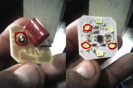
The Design
A filter capacitor in a capacitive power supply will mostly blow-of due to an insurge of voltage higher than its rated value. For example if the filter capacitor breakdown voltage is 50V, and if the surge voltage exceeds this limit could instantly cause the capacitor to explode or gas.
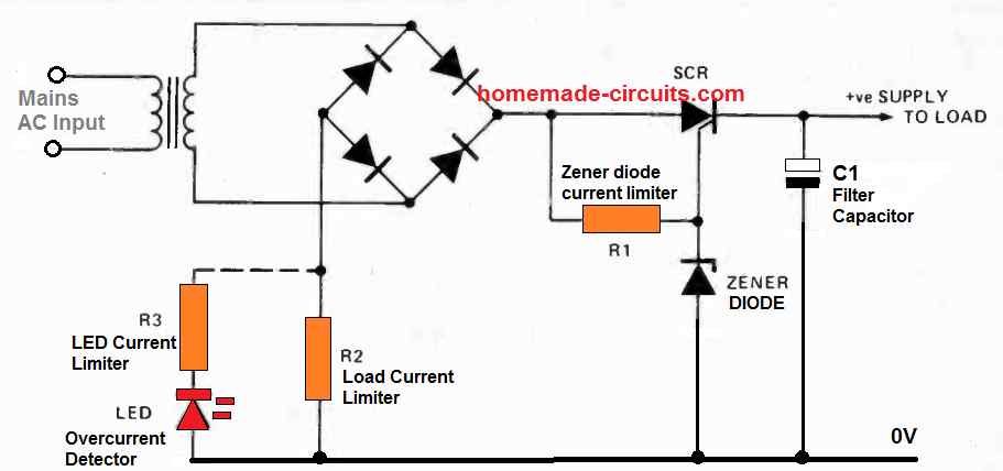
A rather simple solution to protect the vulnerable parts in a capacitive transformerless power supply such as the capacitors and the LEDs is to introduce a shunt regulator circuit as indicated in the following diagram:
Circuit Diagram
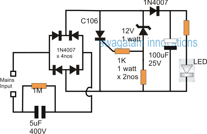
Here the SCR forms the main element for curbing the initial high voltage, high current surge and to ensure a regulated constant supply regardless of the input fluctuations.
If we recall, this concept has been already discussed in one of my earlier posts titled how to make a high current transformerless power supply circuit
Circuit Operation
The idea here is to switch ON the SCR or a triac as soon as the input supply tries to surpass the stipulated safe voltage limit of the circuit, which in turn depends on the indicated zener diode voltage.
Referring to the above SCR shunt circuit for protecting capacitive LED drivers, whenever the input from the mains capacitor tends to go above 12V, the zener diode conducts fully, triggering the SCR, and causing its anode cathode leads to short circuit the supply instantaneously. This response becomes enough to stop the voltage to rise any further and ensure that it's limited within the assigned 12V range.
The stage comprising the SCR, the zener and the 1K resistors act like a high current zener diode and is employed here since the input current is much higher and beyond the capacity of a normal 1 watt zener diode, however for low current transformerless power supply circuits the SCR and the 2nos 1K resistors may be eliminated and only the 12V zener could be used for the intended regulation.
Using High Voltage Transistor
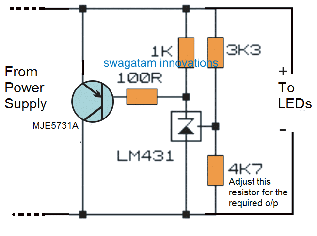
Another effective shunt regulator could be built using a high voltage transistor and a variable zener diode, as shown below:


Questions & Answers
Thx swagatam. nice work. limited space in smd board to implement that, instead i added C1 on another side parallel to existing one & R1 series to LED line, but I'll test that circuit, and Happy Ramzan!
Iwanna post some interesting Electronic articles here, pls gv me ur gmail id.
you are welcome Max, you will need to include only the 4 components, the SCR, the two 1 K and the zener, rest are already present in your board…and these can be made into SMD and easily accommodated in the existing board.
the other simple remedy is to use an inductor in series with the supply…because inductors can be quite good at suppressing switch ON surges.
you can definitely post innovative articles in this site…it will be greatly appreciated.
Hello SWAGATAM,
I continue here, now i have another question, can i remove 400V 5uF and 1M Resistor ?, take too much space on my pcb 🙁
Should i use another way to get what i wish ? (5v 200mA)
Is there another way like high voltage regulator (LR645) ?
Thanks
Best regards.
Oops, i mess something, i need also 3,3v , so i use two ams1117 regulator behind 12vdc , but i only use 5v and 3.3v
Hello Stévanovitch,
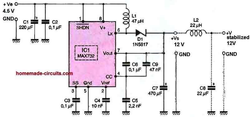
yes you can try the circuit as shown below if the IC is accessible to you
https://www.homemade-circuits.com/2012/03/how-to-make-simplest-and-best.html
AMS1117 can be incorporated with the above IC for getting the other desired lower outputs
Hello SWAGATAM,
LR645 and DN2450 is also too expensive.
I have to find a way wich is low coast and not energy consumer (…)
Now, do you think a can find a way with LR8N8 ? and find a way to get up to 30mA
I don't really know how to do this .
Best regards.
Thanks.
…yes it may be possible by using an outboard transistor, as explained in the following concept…the transistor could be any 500V rated PNP BJT
https://www.homemade-circuits.com/2015/12/lm317-with-outboard-current-boost.html
Thanks , very interesting !
May i disturb you for any other question about that ?
where should i post , in the new link ? or this one ?
You can post it under the above link
Can I use bt136 in the place of c109
yes it work although BT136 is a triac
First picture is not showing.
I am trying to use MB10s with an 8mm 2Chip LED so that I can use the LED without worrying for the polarity but the brightness is very less. What can I do to increase the brightness. Input voltage is around 5V AC
rectifier bridge will drop 0.7 + 0.7 = 1.4V, so 5 – 1.4 = 3.6V, that looks fine if the LEd is the normal 3.5V rated
by the way the MB10 is rated only at 0.8A, and will be extremely hot at this full current level.
what is your LED amp rating??
you may have modify the bridge current accordinly
Hello swagatam,
here in this circuit X rated capacitor used to step down the voltage ….but for the 5uf 400V capacitor how much voltage will get drop down ….this has any calculations ?? how much voltage will get before bridge and after bridge….
can i use a 15v zener diode for a 14v output
yes it will do, it will limit to 15V max
Hello swagatam
We looking for a topology that will provide a constant 12 vdc output at 1 amp, over a 5 to 1 input voltage range, we can do it with a switch mode, however the transformer and the size of the circuitry becomes very large, a transformer less topology looks interesting, our input voltage is 120 to 600 v @ 60hz, any ideas?
Andrew
Hi Andrew, according to me the exact same configuration could be tried, except the shown SCR which must be replaced with a 1kv SCR such as the TYN1012RG.
The input 5uF capacitor will also need to be replaced with a 20uF/1000V capacitor for achieving 1 amp output
Swag
Thank you for your reply, will try and let you know how it works
Andrew
you are welcome!
Hi swatam
I tried the first circuit. Every thing is cool fine, but 12v 10w led is blinking due to ripples. I tried with 1000uf electrolite capacitor, but the proplem is still same. How can i solve this issue
Hi Raees, It could be due to insufficient current. A 12V 10 watt led will require 0.8 amp current, so the input capacitor will need to be around 16uF/400V, which value did you use in your set up?
Thanks for reply
I understand. I used 2.2 uf pp capacitor. Actually i require 300mA current, so i should add more pp capacitor to obtain exact currentagain thanks a lot. May u live long sir. Your valuable suggestions are always regarded.
Thanks Raees, yes you are right. For 300mA you may require a 6uF/400V capacitor.
Pueden publicar diseño en placa pcb para imprimir
I am Sorry, PCB is not available for this design
Hi, my friend Swagatam!The first circuit is very interesting. Some questions:
Respectfully, Jorge
Hi, my friend Jorge,
Sorry I did not understand your first question. Can you explain more.
For an LDR based circuit you can try the first circuit from the following article. Use only the section which comes after the bridge rectifier.
https://www.homemade-circuits.com/simple-led-automatic-daynight-lamp/
Hi, my friend Swagatam!
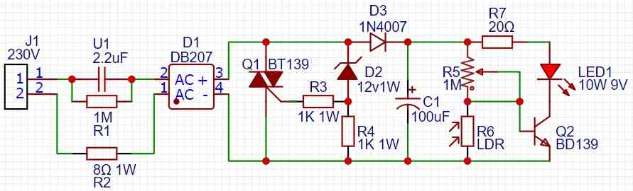
I combined 2 diagrams. Please take a look and make the additions, if necessary.
The task was to connect a 10 watt LED with a voltage of 9 volts (less than the nominal value of 12 volts). The current consumption is 150 milliamps in this case.
I calculated the R2 and R7 resistors using the formulas from your article on calculating the capacitance of a capacitor and a resistor for a transformerless power supply. Is it correct?
Here is a link to my diagram. Look here please.
Respectfully,
Jorge
That looks great my friend,
However there are some issues in the schematic.
The 9V 10 watt LED will require almost 1 amp current which cannot e obtained from the capacitive circuit.
The 20 ohm resistor can be replaced with a
12 – 9 / 1 = 3 ohm resistor.
The R2 resistor can be also removed.
You can also consider using the LAST power supply circuit from this article, which looks very promising and more efficient than the above concept:
https://www.homemade-circuits.com/high-current-transformerless-power-2/
Thank you very much for your comments!

 .
.
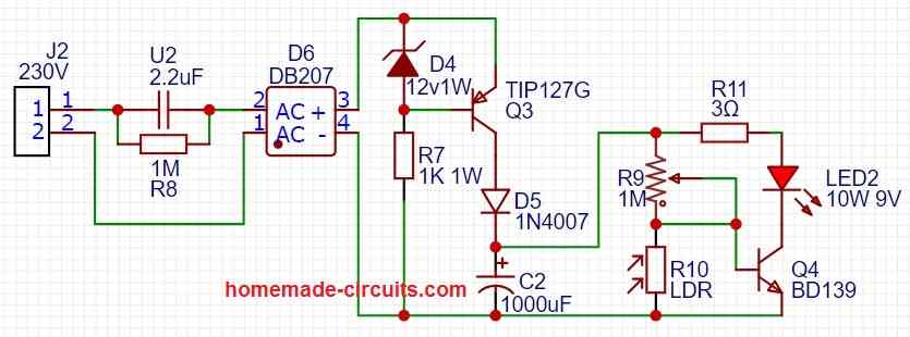
I changed the circuit, please check again.
When the circuit is assembled, I will definitely send links to the photo of the finished circuit in the comments.
In fact, you are very helpful in mastering electronics. I have taken many of the designs from you. You make it easy and easy to understand.
On the basis of some of your projects, I made Christmas electronic toys in the form of balls.
For Christmas tree I used this circuit
You can see short video for all electronic toys here.
Thank you again for your personal help.
Respectfully,
Jorge
Thank you so much Jorge,
Your Christmas toys looks so beautiful with so many twinkling LEDs. I am sure the all the readers here we love them.
The new schematic using the zero crossing detector looks good, however I am a worried about the TIP127. When the AC is at its peak and the transistor in its non-conducting state, there could be as high a 310V DC across the emitter/collector of the transistor. I think for maximum safety it should replaced with a MJE350 transistor.
According to me the advantage of this circuit is low heat generation, whereas the triac circuit could generate high amount of heat.
If you think the triac circuit is more convenient, you can try that instead.
Thank you!
I have an idea!!!
May I use Mosfet, for exapmhle, IRF740 instead MJE350?
That seems to be a great idea, you can definitely give it a try.
Yes!
I read it in your article:
https://www.homemade-circuits.com/how-to-replace-transistor-with-mosfet/
It should be a P channel mosfet actually,…. I guess IRF740 is an N channel mosfet, so it might not work.
Yes, I understand this! It was so idea to use MOSFET, I will experiment with it in few days.
Thank you, my friend.
Sure, No problem, please try a P-channel mosfet and let me know the results.