In this post I will comprehensively explain about reed switch functioning, and how to make simple reed switch circuits.
What is Reed Switch
Reed switch also called reed relay, is a low current magnetic switch with a concealed pair of contacts that close and open in response to magnetic field near it. The contacts are concealed inside a glass tube and its ends terminated out of the glass tube for external connection.
And with around a billion operation specification, the functional life of these devices also look very impressive.
Moreover, reed switches are cheap and therefore become suitable for all types of electrical, electronic applications.

When was Reed switch Invented
Reed switch was invented way back in the year 1945, by Dr. W.B. Ellwood, while being employed at the Western Electric Corporation, in the USA. The invention appears to be a lot advanced than the period when it was invented.
Its immense application advantages continued to be unnoticed by the electronic engineers, until the recent times when reed switches are becoming a part of many crucial electronic and electrical implementations.
How Reed Switches Work
Fundamentally, a reed switch is a magneto-mechanical relay. To be more precise a reed switch working is initiated when a magnetic force is brought near it, which results in the required mechanical switching action.

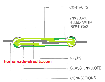
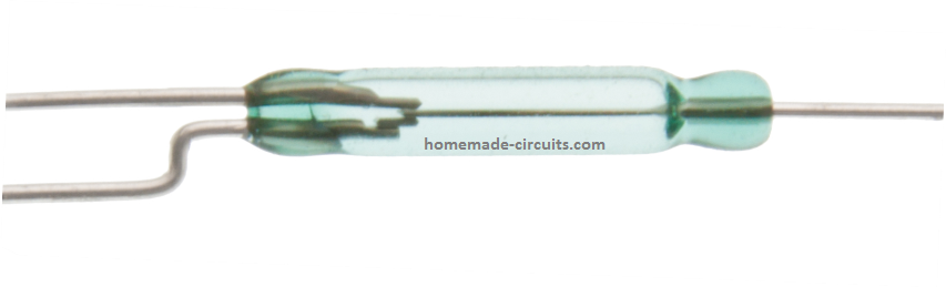
A standard reed relay switch can be witnessed as shown in the above figure. It is made up a pair of flattened ferromagnetic strips (reeds) which are hermetically sealed in a tiny glass tube.
The reeds are clamped firmly on either ends of the glass tube in such a way that their free ends are slightly overlapped at the center with a separation of approximately 0.1 mm.
During the sealing process the air inside the tube is pumped out and is replaced by dry nitrogen. This is crucial to ensure that the contacts work in an inert atmosphere which helps to keep the contacts corrosion free, eliminate air resistance, and make it long lasting.
How it Works
The basic working of a reed switch can be understood from the following explanation
When a magnetic field is introduced near a reed switch either from a permanent magnet or from an electromagnet, the reeds being ferromagnetic turn into a part of the magnetic source. This causes the ends of the reeds to acquire opposite magnetic polarity.
If the magnetic flux is adequately strong, attract the reeds towards each other to an extent which overcomes their clamping rigidity, and their two ends establish an electrical contact at the center of the glass tube.
When the magnetic field is removed, the reeds lose their holding power and the strips spring back to their original position.
Reed Switch Hysteresis
As we know that hysteresis is a phenomenon in which the system is unable to activate and deactivate at a particular fixed point.
As an example, for a 12 V electrical relay, the activation point may be 11 V, but its deactivation point may be somewhere around 8.5 V, this time lag between the activation and deactivation points is known as hysteresis.
Similarly, for a reed switch, the deactivation of its reeds may require the magnet to be moved much farther away from the point at which it was initially activated.
The following image explains the situation clearly
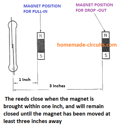
Typically, a reed switch will close when the magnet is brought at a distance of 1 inch from it, but it may need the magnet to be moved around 3 inches away to open the contacts to its original form, due to magnetic hysteresis.
Correcting Hysteresis Effect in Reed Switch
The above hysteresis issue can be reduced to a geat extent by simply introducing another magnet with an inverted N/S poles at the opposite side of the reed switch, a shown below:
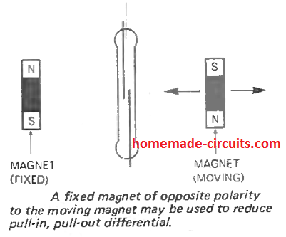
Make sure that the left side fixed magnet is not within the pull-in range of the reed switch, rather at some distance away, otherwise the reed will remain closed and will open only when the right side magnet is brought too close to the reed.
Therefore, the distance of the fixed magnet must be experimented with some trial and error until the right differential is achieved, and the reed activates sharply at a fixed point by the moving magnet.
Creating "Normally-Closed" Type Reed Switch
From the above discussions we know that typically the contacts of a reed switch is 'normally open' type.
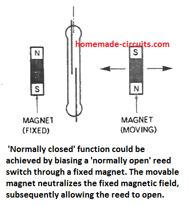
The reeds close if a magnet is held close to the device body. But, there may be certain applications in which the reed may be required to be 'normally-closed' or switched ON, and switch OFF in the presence of a magnetic field.
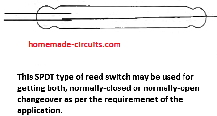
This can easily be achieved either by biasing the device with a complementing nearby magnet as demonstrated below, or by using a 3 terminal SPDT type of reed switch as indicated in the second diagram below.
In the majority of systems in which a reed switch is operated through 'a permanent magnet, the magnet is installed over a moving element, and the reed is installed over a fixed or constant platform.
However, you may find several programs where both the magnet and the reed has to be positioned over a fixed platform. The ON/OFF operation of the reed in such cases is then achieved by distorting the magnetic field with the help of an external moving ferrous agent, as explained in the following paragraph.
Implementing Fixed Reed/Magnet Operation
In this set up the magnet and the reed are kept significantly close by, which enables the reed contacts to be at normally-closed situation, and it opens as soon as the external distorting ferrous agent moves past between the reed and the magnet.
On the other hand, the same concept can be applied for getting exactly the opposite results. Here, the magnet is adjusted to a position which is just enough to keep the reed in normally-open position.
As soon the external ferrous agent is moved between the reed and the magnet, the magnetic force gets enhanced and reinforced by the ferrous agent which instantly pulls-in the reed switch and activates it.
Operating Planes of a Reed Switch
The following figure shows different linear planes of operation for a reed switch. If we move the magnet across any of the planes a-a, b-b, and c-c, will allow the reed to operate normally. However, selecting the magnet can be rather crucial if the mode of operation is across the b-b plane.
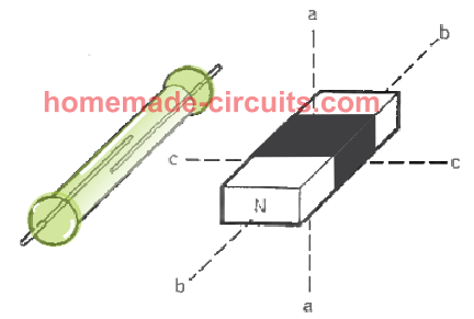
Additionally, you may find spurious or false reed triggering due to negative peaks from the magnet's field pattern curve.
In situations where the negative peaks are high, the reeds may switch ON/OFF several times as the magnet moves past across the end to end length of the reed.
Activation of the reed through a rotational movement can be also implemented successfully.
To achieve this, you can use among the many set ups shown below:
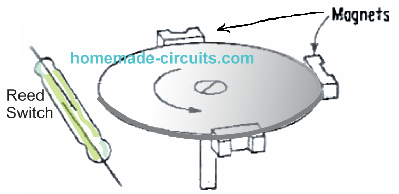
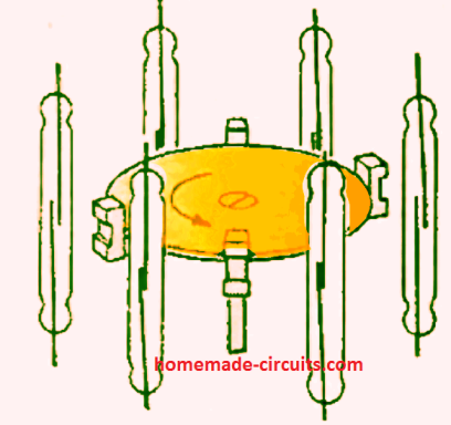
FIGURE B
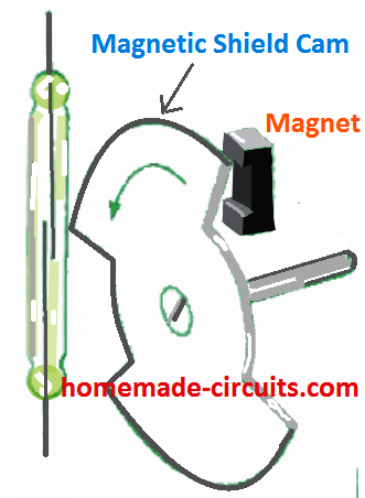
FIGURE C
It is also possible to use a rotational motion for triggering a reed switch set up. In figure A and B, the reed switches are installed in a fixed position, while magnets are attached with the rotating disc which causes the magnets to move past the reed switch on each rotation, switching the reed ON/OFF correspondingly.
In figure C, the magnet and the reed switch both are stationery, while a specially carved magnetic shield cam is rotated between them such that the cam cuts the magnetic field alternately on each rotation causing the reed to open and close in the same sequence
Rotary motion may also be used to actuate a reed switch, In A and B the switches are stationary and the magnets rotate. In examples C and D both the switches and the magnets are stationary and the switch operates whenever the cutout portion of the magnetic shield is between magnet and switch.
Switching rates can be adjusted one second to well over 2000 per minute simply by changing the rotating disc speed.
Operating Life of Reed Switches
Reed switches are designed to have extremely high working life span which may be range from 100 million to 1000 million open/close operations.
However, this may be true only as long as the current is low, if the switching current through the reed contacts exceed the maximum rated value, then the same reed might fail within a few operations.
Typically, reed switches are rated to work with current within a range of 100 mA to 3 Amps depending on the size of the device.
The maximum tolerable value is specified for purely resistive loads. If the load is capacitive or inductive, in that case the contacts of the reed switch must either be substantially derated or appropriate snubber protection and reverse EMF protection applied across the reed terminals, as shown below:
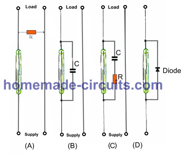
Adding Protection against Inductive Spikes
Any of the above four simple methods an e employed for enabling protection to a reed switch from inductive or capacitive current spikes.
For an inductive load such as a relay coil with a DC supply, a simple resistor shunt rated at 8 times more than the relay coil will be just enough to keep the reed relay safe from the relay coil back EMFs, as shown figure A.
Although this may slightly increase the idle current flow in the reed but that won't harm the reed anyway.
The ersistor can be replaced with a capacitor also for enabling a similar kind of protection, as shown in figure B.
Typically, a resistor capacitor protection network is applied as indicated in figure C, in case the supply is an AC. The resistor can be a 150 ohm 1/4 watt, and the capacitor can be anything between 0.1 uF and 1 uF.
This method has been proved to be the most effective, and has been successful in keeping the reed safe from motor starter switching for over a million operations.
The value R and C can be determined through the following formula
C = I^2 / 10 uF, and R = E / 10I( 1 + 50/E)
Where E is the closed circuit current and E is the open circuit voltage of the network.
In figure C we can see a diode connected across the reed. This protection works well in DC circuits with inductive load, although the polarity of the diode must be correctly implemented.
High Current Reed Swithcing
In applications which require heavy current switching using a reed switch, a triac circuit is employed for switching the heavy current load and a reed switch is used for controlling the gate switching of the triac as shown below
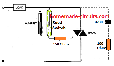
The gate current being significantly less than the load current, the reed switch will work efficiently and allow the triac to be switched wit the high current load. Even minute reed switch can be applied here, and will work without issues.
The optional 0.1 uF and the 100 ohm RC is a snubber network is for protecting the triac against high current inductive spikes, if the load is an inductive load.
Advantages of Reed Switch
A great advantage of the reed switch is its capacity to work very efficiently while switching low magnitudes of currents and voltages. This can be a significant problem when a regular switch is used. This is because of lack of adequate current to eliminate the resistive surface layer normally associated with standard switch contacts.
On the contrary, a reed switch as a result of its gold-plated contact surfaces and inert atmosphere works successfully for over a billion operations without any issues.
In one of the practical tests in a reputed USA company lab, four reed switches were powered with 120 ON/OFF sequences per second through a load working with 500 micro-volts and 100 microamps, dc.
In the test each of the reeds could complete 50 million closures consistently with not a single occasion showing a switched resistance beyond 5 ohms.
Reed Switch Failures
Although extremely efficient, reed switch may show a tendency to fail if the operated under higher current inputs. High current causes the contacts to erode which is also commonly seen in regular switches.
This erosion results in tiny particles which are also magnetic to collect near the gap of the contacts and somehow create a bridging across the gap. This bridging of the gap causes a short circuit and reeds seems to be fused permanently ON.
So actually it is not due to melting of the contacts, rather the shorting due to the collection of the eroded particles that causes the reed contacts to seem like they have melted and fused.
Specifications for a Standard Universal Reed Switch
- Maximum voltage = 150 V
- Maximum current = 2 amps
- Maximum power = 25 watt
- Max. initial resistance = 50 milliohms
- Max. end-of-life resistance = 2 Ohms
- Peak breakdown voltage = 500 V
- Closure rate = 400 Hz
- Insulation resistance = 5000 milliohms
- Temperature range = -55 degrees C to +150 degrees C
- Contact capacitance = 1.5 pF
- Vibration = 10G at 10-55Hz
- Shock = 15G mini mu m
- Life at rated load = 5 x 10^6 operations
- Life at zero load = 500 x 10^6 operations
Applications Areas
- Hydraulic brake fluid level indicator, where feasibility fundamentally relies on straightforwardness and ease of use.
- Proximity counting, delivering an incredibly simple approach to recording the passing of ferrous objects across a set predetermined point.
- Safety interlock switching, offering extraordinary stability and ease-of-use of applications to intricately mechanized designs. Here, embedded reed switches are used to connect a circuit to light up a cautionary lamp or prompt the next stages of operation.
- Sealed switching in inflammable environments, circumvents combustion possibility; also in dust packed atmospheres where standard open switches could be hard to rely on; and particularly in cold weather where regular switches might simply freeze up.
- In radioactive surroundings, where magnetic working helps to preserve credibility of shielding.
Some other application circuits published in this website
Float Switch: Reed switches can be used for effective corrosion free float switches water level controllers. Since reed switches are sealed, water contact is avoided and the system works infinitely without any issues.
Patient Drip Alarm: This circuit uses a reed switch to activate an alarm when the drip package connected to a patient becomes empty. The alarm enables the nurse to know the situation immediately and replace the empty drip with a new package.
Magnetic Door Alarm: In this application, a reed switch activates or deactivates when an adjacent magnet is moved by the opening or closing of a door. The alarm alerts the user regarding the operation of the door.
Transformer Winding Counter: Here, the reed switch is operated by a magnet attached on a rotating winder wheel, which allows the counter to get a clock signal for each winding rotation from the reed activation.
Gate Open/Close Controller: Reed switches also work great as solid state limit switches. In this gate controller circuit, the reed switch limits the gate opening or closing by shutting off the motor whenever the gate reaches its maximum sliding limits.


Comments
Thank you for your very informative and useful content
Thank you!
Hello again, Swagatam!
I have a question after reading you interesting article.
How would I find the correct Inductor to trigger the correct reed switch, if both a circuit with the inductor, is to close a normally-open reed switch on another, physically separate circuit, are both being run off of 6VDC and at 0.1A?
I tried to post an image, but couldn’t.
I have everything else figured out except that I can’t find information about how to find the correct switch+inductor pair given the low power. of each circuit. I do need each respective load to have its own voltage source, for specific reasons, so connecting the two circuits anywhere is a no-go and the reason I need the first circuit to switch on the second one via this inductor+reed switch pairing.
Thank you very much!.
Thank you Kris,
I do not have the exact formulas for calculating the inductor for switching a reed relay, I guess this can be found with some trial and error. You can probably try 50 to 100 turns of 30 SWG wire over the reed switch and check how it responds.
Hello, Swagatam! I was wondering whether I’d need to try wrapping my own wire, so now I know, though I was hoping I was just missing something obvious about pairing these two components because I’ve never done anything like that. But it’s good to try new things.
– I’ve been looking for inductor:reed-switch information online for a number of days, trying different search phrases, but oddly enough, despite all of the times various websites and online textbooks *mention* this pairing, I have yet to find one that gives any details….
– I’ve only seen sales information for high-power AC setups.
– Well, I’ll definitely try your wire-wrap idea and, if I *do* get it to work, I’ll add a comment here to let you know, if that’s OK.
– I’m waiting for a few parts yet so it’ll be some days.
– Thank you for the suggestion!
Thank you Kris,
You can definitely create your own reed relay with coil, by wrapping number of turns directly over the glass of the reed relay. Just make sure the wire is a super enameled copper wire.
Let me know how it goes. All the best to you.
We need a reed switch to control a 12vdc 20 amp circuit. But reed switches will not withstand such a high current Question is-can we buy a reed switch nd a TRIAC circuit in one package for simplification?
Triacs cannot be used for DC switching, you can use a MOSFET based switch, an SSR, or a relay for upgrading a reed switch
Can you kindly send me the circuit diagram for 0_190ohm reed switch level sensor and the values of resistors to be used
sorry I did not correctly understand your requirement, what is 190 ohm reed switch level sensor??
how do we use a reed switch to make an alarm indicating that my hot water is ready in a water heater…… may you please explain its block diagrams….thank you.
reed relay cannot b used to sense heat, therefore it is not possible to implement a reed relay for temperature indication.
Thanks for your Ideas Sir,
thank you very much for this very interesting article about reed-switches
It’s my pleasure, Glad you liked the post!