• Skip to main content
  • Skip to primary sidebar

Homemade Circuit Projects

Need circuit help? Post them in the comments! I've answered over 50,000!

Blog | Categories | About | Hire Me | Contact | Calculators-online
You are here: Home / Games and Sports Projects / Electronic Scoreboard Circuit Using IC 4033 Counter

Electronic Scoreboard Circuit Using IC 4033 Counter

Last Updated on May 21, 2026 by Swagatam 12 Comments

A simple multi-digit electronic score board system can be built using a basic 4033 IC counter circuit. The whole procedure is explained in the following article.

Table of Contents
  • Circuit Operation
    • Using IC 4033 IC Modules

So far we have learned quiet a lot about this interesting IC 4033 through the following posts that have comprehensively discussed the pinouts and cascading procedures of the chip.

4033 pinouts

cascading 4033

In this post I have explained how to make a simple counter circuit for counting number of positive pulses applied manually in the form of high logics at the input of the IC.

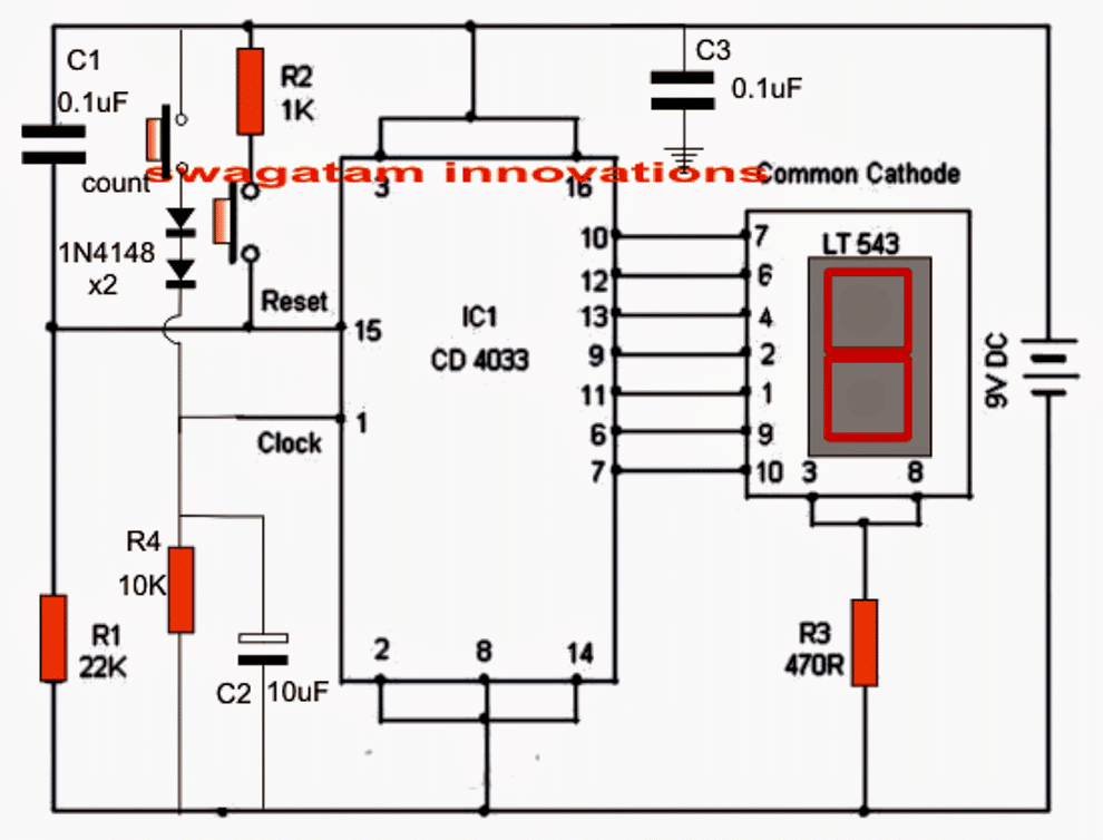
Referring to the shown simple counter circuit diagram, the IC 4033 which is a Johnson's counter/divider display decoder driver IC is configured solely for the required counting actions.

Circuit Operation

The circuit is pretty straightforward, the various pinouts used in the configuration may be understood with the following points:

Pin#1 is the clock input which is connected to a push switch via a couple of diodes and is also terminated to ground through R4 and C2.

Here the push-switch is used for pulsing the input of the IC for getting the corresponding count over the connected common cathode display across its output pins: 7,6,11,9,13,12,10.

The two diodes make sure that the IC responds only to legit switching and not to accidental spurious triggers.

R4 and C2 prevent debouncing effect that could occur during the clocking operations.
With every push of this switch, the output advances by one digit until it reaches 9 after which the display returns back to zero in order to repeat the cycle.

Another push switch can be seen connected at pin#15 of the IC 4033, this is used for resetting the IC output reading to zero at any desired instant in the course of the counting process.

C1 ensures that the IC always displays a 0 over the connected display during power switch ON.

R1 ensures the required logic zero to pin#15 of the IC for making it functional.

C3 is the decoupling capacitor, imperative for all logic ICs as per the standard rules.
Using IC 4033 IC Modules

The simplest and the best method is to use many such modules as explained above and arrange them in line for acquiring the required number of displays on the scoreboard.

Suppose we need a 4 digit scoreboard for the application, then 4 of these modules may be fixed one beside the other for implementing the scoreboard display system.

Now by simply pressing the relevant push buttons one could allow the desired number to appear in the relevant slot of the multi-digit display board.

Using the above method provides the facility of setting/resetting of any particular digit as per individual wish or requirements. This is simply done either by using the clock push button, the reset button or perhaps both during the counting operations.

Thus the above suggested electronic scoreboard becomes very easy to handle even by novices in the filed, or by any layman.

You'll also like:

  • led2BtimerLED Timer Indicator Circuit for Board Games
  • fastest finger first game5 Simple Fastest Finger First Circuits Explained
  • DSC0410 1Making an Automatic Stopwatch for Runners, Athletes and Sportpersons
  • tenns ball throwing machine circuit compressedTennis Ball Throwing Machine Circuit

Filed Under: Games and Sports Projects Tagged With: 4033, Counter, Electronic, Scoreboard

About Swagatam

I am an electronics engineer and doing practical hands-on work from more than 15 years now. Building real circuits, testing them and also making PCB layouts by myself. I really love doing all these things like inventing something new, designing electronics and also helping other people like hobby guys who want to make their own cool circuits at home.

And that is the main reason why I started this website homemade-circuits.com, to share different types of circuit ideas..

If you are having any kind of doubt or question related to circuits then just write down your question in the comment box below, I am like always checking, so I guarantee I will reply you for sure!


Previous Post: « Treadmill Motor Speed Controller Circuit
Next Post: Blinking an LED with Delay – Arduino Basics »

Reader Interactions

Questions & Answers

Total Posts: 12
Newest Oldest
Anna
September 25, 2021 • 5 years ago #98455

Hi there

Is it possible to use a remote controller with the – Digital Counter DC LED 4 Digit 0-9999 Up/Down Plus/Minus Panel Counter Meters? I would like to have electronic scoreboards for playing table tennis? If so do the RF 433Mhz Transmitter/Receiver Modules still apply?

Cheers

Reply
SwagatamAdmin
September 25, 2021 • 5 years ago #98476

Hi, yes definitely a remote controlled operation is possible with the above circuit, using the 433MHz module. You simply need to configure the relay contacts of the 433MHz receiver with the “count” switch of the circuit

Reply
Radhika Nikum
February 5, 2020 • 6 years ago #76030

On Simulating this circuits do not work?

Reply
Robin Closen
August 7, 2017 • 9 years ago #52262

Can I use this with a scoreboard digit made from 7 12 volt LED strip lights ?

Reply
SwagatamAdmin
August 7, 2017 • 9 years ago #52265

you will require BJT current amplifier stages for operating the strips, the IC directly won't be able to drive them

Reply
Miraj Htm
February 26, 2016 • 10 years ago #39163

another question. can i use down button in this circuit( sometimes i need to count down)

Reply
SwagatamAdmin
February 26, 2016 • 10 years ago #39173

sorry there is no "down" feature in this circuit

Reply
Miraj Htm
February 26, 2016 • 10 years ago #39162

i tried but only 8 is illuminated. nothing happen when i press button

Reply
SwagatamAdmin
February 26, 2016 • 10 years ago #39172

with every press of the "count" button there will be an increment of 1 digit on the readout…

check your IC connections.

Reply
SwagatamAdmin
August 1, 2015 • 11 years ago #32818

John, you can use CD 4026B instead of 4033, for the display you can use any 7-digit common cathode type module

Reply
John Bufete
August 1, 2015 • 11 years ago #32810

Sir, the LT 543 and CD 4033 are not available in our place, what are the possible options or replacements for these? I'm a student sir and I always browse this website for my projects. Thank you

Reply
Cycle Zone
October 18, 2014 • 12 years ago #26602

Dear plz give me an auto polarity changer circuit

Reply

Need Help? Please Leave a Comment! We value your input—Kindly keep it relevant to the above topic! Cancel reply

Your email address will not be published. Required fields are marked *

Primary Sidebar


Categories

  • Arduino Projects (95)
  • Audio and Amplifier Projects (134)
  • Automation Projects (18)
  • Automobile Electronics (103)
  • Battery Charger Circuits (89)
  • Datasheets and Components (109)
  • Electronics Theory (150)
  • Energy from Magnets and Earth (40)
  • Games and Sports Projects (11)
  • Grid and 3-Phase (20)
  • Health related Projects (27)
  • Home Electrical Circuits (13)
  • Indicator Circuits (16)
  • Inverter Circuits (100)
  • Lamps and Lights (163)
  • Meters and Testers (72)
  • Mini Projects (28)
  • Motor Controller (68)
  • Oscillator Circuits (30)
  • Pets and Pests (15)
  • Power Supply Circuits (91)
  • Remote Control Circuits (50)
  • Security and Alarm (65)
  • Sensors and Detectors (107)
  • SMPS and Converters (46)
  • Solar Controller Circuits (62)
  • Temperature Controllers (44)
  • Timer and Delay Relay (50)
  • Voltage Control and Protection (44)
  • Water Controller (37)
  • Wireless Circuits (31)


Circuit Simulator

circuit simulator image


Subscribe to get New Circuits in your Email


Other Links

  • Privacy Policy
  • Cookie Policy
  • Disclaimer
  • Copyright
  • Videos
  • Sitemap

People also Search

555 Circuits | 741 Circuits | LM324 Circuits | LM338 Circuits | 4017 Circuits | Ultrasonic Projects | SMPS Projects | Christmas Projects | MOSFETs | Radio Circuits | Laser Circuits | PIR Projects |


Recent Comments

  • Swagatam on 2 Cool 50 Watt Inverter Circuits for Students and Hobbyists
  • Swagatam on The Perfect FM Radio Circuit using TDA7000 IC
  • Swagatam on 9 Simple Sine Wave Generator Circuits Explored
  • way on 2 Cool 50 Watt Inverter Circuits for Students and Hobbyists
  • Athull on The Perfect FM Radio Circuit using TDA7000 IC

Social Profiles

  • Twitter
  • YouTube
  • Instagram
  • Pinterest
  • My Facebook-Page
  • Stack Exchange
  • Linkedin

© 2026 · Swagatam Innovations