You might have probably come across these fantastic high power, high efficiency LED modules and wondered how do you make these? Here I have explained how to make a 100 watt LED flashlight out of it?
Introduction
The article revises the datasheet of this LED module and explains a simple driver circuit which can be used for operating it safely for the intended lighting purpose.
So far we have learned about LEDs with rather smaller features and applications. However the present article finds out how a LED module in the order of 100 watts can be actually used for illuminating a house at costs probably 5 times lower than the conventional lighting devices.
100 Watt LED Module Image
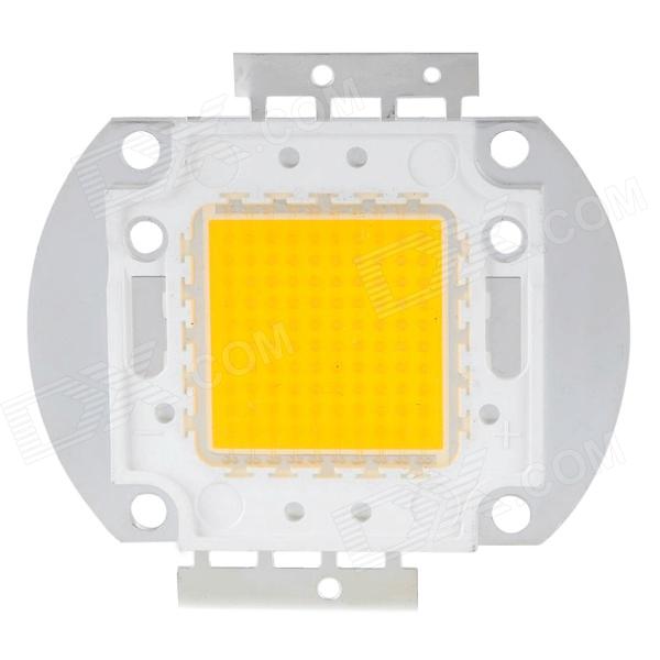
We have all studied a great deal about LEDs and about their high-efficiency with power consumption.
The LED technology has helped us to design and incorporate very high intensity light installations at minimal consumptions as compared to the other conventional form of lighting concepts.
Lower power consumption also means low heat emissions, which again is an added feature and helps to keep the crucial issue of global warming at bay when LEDs are utilized.
As days pass by, technology keeps on improving and we are able to witness many incredible and unbelievable results with these outstanding lighting devices.
The 100 watt LED module is one such marvel of modern science which has created a breakthrough in the field of LED lighting.
Not surprisingly, the device is able to generate an astonishing 6500 lumens of light intensity at a consumption of mere 100 watts, but the interesting part is the size, which is barely 40 square mm.
The saving made by these devices is estimated to be five times more than any other form of light producing device and the if we compare the specified intensity of 6500 lumens, that corresponds to an excess of 500 watts light power that might be acquired from a halogen lamp.
Let’s discuss the important specifications of this amazing LED in brief and in such a way that even a layman understands:
100 Watt LED Datasheet
Typically the preferred color is white, as that produces the most favorable and desirable illumination for all applications.
- The power consumed is 100 watts for optimal performance.
- The emanated heat for the specified white color is up to 6000 Kelvin.
- The intensity of light generated with the above specs is a staggering 6500 lumens.
- Typical operating voltage of the device is around 35 volts.
- The current required for producing the above light intensity is around 3 Amps.
- ESD level is safe and very high up to 4000 V.
- The safe operating temperature level is very wide, ranging from minus 40 to 110 degrees Celsius.
- The optimum angle of viewing is also wide, up to 120 degree.
- Dimension of the unit is truely mini, the height being 4.3 mm, length 56 mm and width 40 mm only.
Typical Specifications
- LED Type: 100W COB LED
- CRI: Ra70-80/ Ra80-85/ Ra90-95 / Ra95-98
- IF (Forward Current): 3500mA
- VF (Forward Voltage): 29-34volts
- Chip Category: Bridgelux
- Power Output: 100 Watt
- Angle of Beam: 120 degree
- Illumination Magnitude: 10000-14000lm
- Substrate: high-grade copper
- CCT: 3000K, 4000K, 5000K, 6000K.(any CCT can be customized)
- Main application areas: Spotlight, Roving head light, light in stage shows, photography, High intensity rescue floodlight, etc
The specification narrated are sufficient for illuminating a 20 square meter space amply, almost at flood light levels ….. baffling.
Main Features of the 100 Watt LED
The advantages include the following:
High power light output without degradation even after long usages.
Highly robust mechanical specifications, involving less wear and tear and high resistance to changing atmospheric hostilities.
The overall performance is consistently optimal throughout the operating life.
Having discussed the above features of the proposed 100 watt LED lamp, it would be interesting to also learn regarding a useful recommended circuit that may be used for driving or operating the device at safe levels.
How to Make a Current Controlled 100 watt LED flood Light Circuit
A simple two transistor, powerful current limiter, LED driver circuit, which can be used for converting the above discussed device into a 100 watt LED flashlight or to be more accurate, a floodlight is described below:
The circuit of a 100 watt LED flood light shown below has been discussed in few of my other articles also, due its versatile and rather straightforward design; the circuit becomes very suitable in places where current limiting at low costs becomes an issue.
Though the discussed designs mostly dealt with low current applications, the present circuit is specifically intended for handling high currents and up to 100 watts and more power.
Circuit Diagram
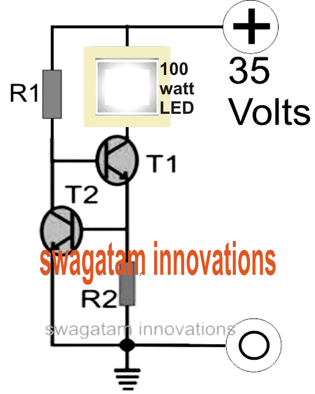
Looking at the figure we can see a couple of transistors are coupled together such that the base of the upper transistor T1 becomes the collector load of the bottom transistor T2.
The upper transistor T1 which actually carries the LED current is quite vulnerable itself, and is not equipped to control the amount of current through itself and the LED.
However since the base current of this transistor decides the amount of collector current that can pass, it simply means that by restricting its base current to some safe specified levels, it might be possible to keep the overall consumption within tolerable limits.
A current sensing resistor connected at the emitter of T1 is used to convert the current consumed, into a potential difference, across it. This potential difference becomes the base trigger for R2.
However as long as this voltage is below 0.6 volts or simply below the minimum forward voltage drop of T2, T2 remains unresponsive, but once it starts exceeding this value, triggers T2 which in turn clamps the base voltage of T1, rendering it inactive.
This instantaneous cut off of the base drive to T1 shuts the LED for some fraction of a second, bringing the current and the potential drop across the current limiting resistor to zero.
This action reverts the circuit to its original stance and the LED is again switched ON.
The process repeats a number of times per second to keep the LED and the current to safe and precisely tolerable limits.
The value of R2 is calculated in such a way that it keeps the potential difference across itself below 0.6 volts until the LED current reaches 100 watts, after which the restricting process begins.
Warning: The LED must be mounted on a correctly optimized heatsink as per the specifications provided in its datasheet..
How to Calculate the Constant Current Limiting Resistor
For calculating R1 you may use the following formula:
R1 = (Us - 0.7)Hfe/Load Current,
where Us = supply voltage, Hfe = T1 forward current gain, Load current = LED current = 100/35 = 2.5 amps
R1 = (35 - 0.7)30/2.5= 410 Ohms,
wattage for the above resistor would be = 35 x (35/410) = 2.98 or 3 watts
Formula for calculating R2 is:
R2 = 0.7/LED current
R2 = 0.7/2.5 = 0.3 ohms,
wattage may be calculated as = 0.7 x 2.5 = 2 watts
For an SMPS driver circuit please refer to this article
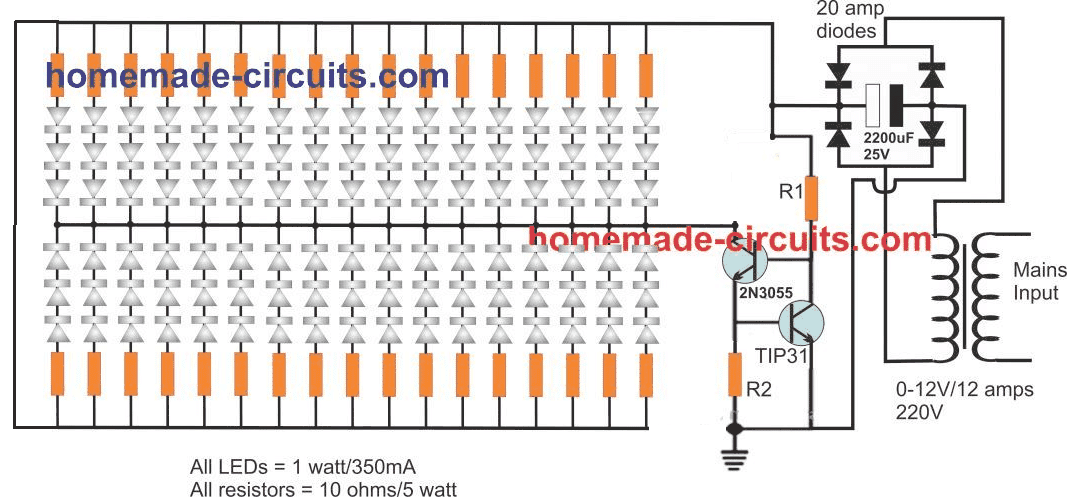
Current Controlled 100 watt LED Lamp complete schematic



Questions & Answers
Hi, yes it is doable.
T1 and T2 are transistors, for your application you may use TIP31 for T1 and 2N2222 for T2.
As per your LED specs the other component values could be as follows:
R1 = 270 ohms, 1 watt
R2 = 0.7 ohms 1 watt
Your calculations and assumptions are perfectly correct, in fact I have aready discussed the idea elaborately here, you can refer it for better understanding:
https://www.homemade-circuits.com/2013/06/universal-high-watt-led-current-limiter.html
…a 1% MFR type resistor will do the job.
I respectfully request you to explain what's incorrect in the above formula and diagram….if you are unable to do it, you can learn it from me further, don't worry I will apologize you for your above ignorance.
I have not built this circuit yet, but you can try TIP35 for T1 and TIP31 for T2
Hi Swagatam
I could not see my post (in the hobby circuits) as well as your reply, which I have been notified in my mail box!
Anyway, please check and confirm if following components would be okay for supplying fixed 5A to the load from a car battery:
R1 = 68R 2Watts
R2 = 0.14R 3.5Watts
T1 = TIP41 (6A)
T2 = TIP31 (3A)
Hi Abu-Hafss,
Which posts are you referring to?
Yes the calculations are approximately correct.
The T1 heat up very quickly …but i only tested at 12v/18A, maybe the low voltage or the high amps cause the T1 to heat up? I used T1,T2 mje3055, R1 390R and R2 0.5R (3w both). Thanks.
yes, when voltage is low, current will be high, you can try TIP35 with heatsink for getting a better response
Hi Swagatam
I referred to the post wherein you recommended me LM338 for fixed 5A supply from car battery. By the way, what would be wiring of LM338 with car battery?
As for this circuit, will it be possible to use it as variable current controller? If yes, how?
Hi Abu-Haafss,
I have no idea what happened to that comment, may be due to some kind of glitch in the system.
Please refer to the following article, you can go for the first circuit shown there:
https://www.homemade-circuits.com/2013/06/universal-high-watt-led-current-limiter.html
I have a 10W LED flood light that I purchased off Ebay. The manufacturer states that the LED itself has a forward voltage of 9-11V with a max current consumption of 1050mA. I do not want to use it at the full current. I'd like to keep it below the max around 900mA. I'd like to be able to do 2 things with it once it is converted over. 1) Use it as a standard flood light on my vehicle and 2) Have the ability of making it flash like an emergency light. Can I use a 2N2222 for T2 and what resistor values do you recommend ?
I think you should use a LM317 IC for your application, the above circuit is crude and should be used only for those applications which does not support the available hi-tech ICs due to high voltage/current parameters.
You can try the first design shown in the following link:
https://www.homemade-circuits.com/2012/11/3-watt-5-watt-led-dc-to-dc-constant.html
For making it flash, you can use a standard IC555 astable circuit and connect its output pin3 to the collector of the 2N2222.
When you switch ON this circuit, will result in flashing of the LEd.
I need Constant Current Driver circuit for 12Volt,20Watts and 10watts LEDs kindly share the simple diagram
you will have to use an smps for this, there's no simple circuit for it
hello! i have 6watt led from ebay and data is 9v-12v dc. @ 380mA. each. i want to run 6-12 of this led at a time. What should i use in the circuit? or, can you kindly make a circuit for that? is it possible to run these led with transformerless power supply? please! Help me. Thanks. 🙂
capacitive type of power supply will not work with these LEDs.
The easiest way is to procure a good quality 12V/2amp SMPS and drive all the LEDs in parallel with this unit.
Can you show me the mentioned circuit? Please???? I want to make 12v/2amp SMPS. will you kindly show me how?
you an make this circuit:
https://www.homemade-circuits.com/2012/03/how-to-make-simple-12-v-1-amp-switch.html
just upgrade the secondary winding from 1amp to approx 2amps by using two parallel wire instead of one. Wind these two wires simultaneously.
I have a 10W LED which has a forward voltage of 9-11V with a max current consumption of 1050mA. Can I run this LED with 7809.
yes, you can do it.
Hi there!
I recently bought a 100W LED which has 34V forward voltage and 3A forward current. What kind of transistors should I use in my case?
Hi,
you can use TIP3055 for T1, and TIP31 for T2
Hello Swagatam Majumdar. Very good website and very useful !!!!
I buy one of this 100w led cool white , But I looking at the datasheet, I do not understand WHICH IS BETTER VALUE OF CURRENT AND VOLTAGE for maximum brightness is achieved without damaging the LED (with heatsink and fan).
I read IF= 3,5 A
Min 32
Typ 34
Max 36
I THINK 3,5 IS MUCH CURRENT BECAUSE P=V.I=34V . 3,5 A = 119 W.
THIS I HAVE: i.imgur.com/DBCJNuI.png
I LIKE BUILD A LIMIT CURRENT A OUTPUT VOLTAGE REGULATOR.
COMPONENTS AND VALUES THAT RECOMMENDED BUY ME TO GET THE MAXIMUM LED LIGHTING WITHOUT BREAKING IT???? ( I WILL PUT IT WITH HEATSINK AND FAN)
MY IDEA IS PUT 34V- 3A OR 33V-3.2 A
but i dont know values using of T1, T2 , R1 AND R2 AND POWER OF THESE what can you tell me??
THANK YOU VERY MUCH
REGARDS.
Hello Harley,
I think you should go for 32V as it looks very optimal, safe and within the reach of an LM338 circuit which I would be referring to you, the above circuit could be relatively crude so I don't recommend it.
You can use a 0-24/5amp transformer, rectify it using a full bridge rectifier and filter the output with a 1000uF/50V cap.
Apply the above output to a LM338 current limiter circuit and use the output from this circuit to illuminate your LED. This would provide an ultimate guarantee to your device….however do not forget about adding a heatsink to the LED.
The LM338 circuit is shown in this link:
https://www.homemade-circuits.com/2013/06/universal-high-watt-led-current-limiter.html
use the first design, replace LM117 with LM338 and calculate R1 from the given formula
….a 0-24V after rectification would output around 34V, which is just suitable for your application, the rest will be handled by the LM338 circuit
Hello and thanks for your fast response.
I I already bought Power DC-DC Boost Converter 150W 10-32V to 12-35V 6A .
You mean it does not serve me this dc-dc boost.
I have little knowledge and no clear to my this mounting.
IS THIS CORRECT?
i.imgur.com/965TvoC.png
IF I CHOOSE OPTION DOWN THE VALUES ARE TIP3055 for T1, and TIP31 for T2
R1 = (32 – 0.7)30/3
= 313 OHMS
wattage for the above resistor would be = 32 x (32/313) = 3.3 WATTS
Formula for calculating R2 is:
R2 = 0.7/LED current
R2 = 0.7/3 = 0.23 ohms,
wattage may be calculated as = 0.7 x 3 = 2.1 watts
IF I WOULD LIKE THE OPTION 1 CIRCUIT HOW FINDING VALUES?
SORRY FOR MY LITTLE KNOWLEDGE.
REGARDS FRIEND.
Harley, the connections shown in the image are perfect, if the boost converter is able to provide the required current/voltage, everything would work satisfactorily.
I would recommend the IC current limiter over the above transistorized version because it's much sophisticated in all respects.
However if you are interested to go for the above, you may do so.
The calculations that you have made are also correct.
Hello Swagatam, really amazing tutorial.
I am new in the world of electronics and would like to know how to wire a 0,12A cooling fan so that it is powered by the same 12v battery that powers the led.
Thank you for your time.
Best regards.
Thanks Miha.
You may do it by simply connecting the motor wires parallel with the battery poles, observing correct polarity
If the motor is rated at a lower voltage, you may use a regulator IC such as 7805, 7806, 7808, 7809 etc whatever may suit your motor.
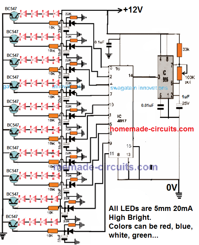
dear sir i want to flash sequentially/(running mode) 4 to 6 nos of 3w color leds from 12v dc source. request circuit instructions.
Dear Jayanath, you can try the following design:
https://www.homemade-circuits.com/2011/12/simple-yet-effective-led-strobe-light.html
First construct the shown design successfully using 5mm LEDs, later I'll explain how to modify it for illuminating high watt LEDs
ok sir i will do and let u know thanks
ckt for 10W LED?
Dear Sir,
Thanks for the setup, could you pls tell the value of T1 and T2. Also in Ebay its advised to give 32 to 35V , Approx 3500mAh. In this stage, i guess 32V is feasible right. Can you please suggest a best transformer-less circuit with best filter with zener protection.
Awaiting for your valuable feedback, thanks in advance.
Dear Anish, you will have to procure a 32V/3amp SMPS and use it with the above circuit for driving the LED
I would like to try a 50 watt version and a 30 watt version, would you change the R value for each curcuit?
you can take the help of the following article and the given formulas:
https://www.homemade-circuits.com/2013/02/make-this-1000-watt-led-flood-light.html
By way of the DC boost converter that utilizes the much higher, reversed polarity fly back voltage from its inductors collapsing magnetic field whilst its oscillating at high frequency. That higher then source and presently AC voltage is then rectified back to DC at the desired higher voltage. Pretty simple stuff when you look at the schematics for any boost/buck converters…
How can you vary the brightness of 100 watt led?
use a variable resistance for R2
Great blog.
Question: what do u use for T1 and T2? Url? Any heatsink requirements?
Question: are R1 and R2 axial resistors?
thanks, heatsinks will be required for T1/T2 depending on the load dimension.
R1, R2 could be axial or any other variant doesn't make any difference.
HI! Like the others; Great site, and thanks for sharing your knowledge! But I wish you could have been a bit more specific this time. An amateur tinkerer like me has no idea what transistors to use. I can build stuff from schematics, and cross reference if I don't have the recommended transistors, but I need to know where to start looking in my scrap box…
I'm experimenting with a similar LED to the one in the picture. I rescued it from a dumpster, so I don't have the specs, but a quick test showed that it works. It has five rows of ten LEDs, and after googeling a bit it seems that that means it's a 100W unit, right? And if so, what would you have used for T1 and T2?
On behalf of noobs the world over, please enlighten us!
(recommendations for 50W and 200W+ setups are also most welcome… 🙂
Hi, thanks
you can use TIP3055 for T1, and TIP31 for T2, these transistors would also work for 50 watt and 200 watt lamps 🙂
Hi, I have a workshop and would like to run 5 x 50w led flood lights in a row,
they would be run from a 240v output genarator.
Can I run them from one driver/transformer or does each LED need a separate supply?
I am out of my depth when it comes to making one so I will have to buy what I need.
Could you please advise me on what I need to get.
Many Thanks
Hi, you can run all the 5 modules from a single adequately rated power supply unit, preferably an SMPS unit.
In between each LED and the supply you will need to insert a current controller stage as shown in the first diagram of the following post:
https://www.homemade-circuits.com/2013/06/universal-high-watt-led-current-limiter.html
LM117 will need to be replaced with LM338
I want to power a 10w led using a 12v lipo batter, i wanted to use the 2nd circuit that you mention here: https://www.homemade-circuits.com/2012/11/3-watt-5-watt-led-dc-to-dc-constant.html I want to also make that flash like emergency lights. I saw that you mention on the comments here for a guy to use "IC555 astable circuit" is that what I need to use, if so, how do I hook it up in the circuit, and where do I purchase it, or can I just do a google search for "IC555 astable circuit"
thank you for your help.
yes you can use any standard 555 astable flasher circuit and drive the LED from a BJT stage connected at pin3 of the IC…..such as a TIP122…connect its base with pin3 via a 10k resistor, emitter to ground (negative) and the LED across collector of the transistor and positive supply.
The battery poles may be then connected to the input of the LM338 circuit and the output of the LM338 to the pin4/8 (positive) and pin1 (ground) of the astable….positive will also connect to the LED as explained above
thank you for your reply, can you tell me what is a BJT, kinda new to this, is there any way you can post a quick wiring diagram of how you are telling me to hoke it up please
you may refer to this article which is quite identical to your requirement:
https://www.homemade-circuits.com/2012/09/led-emergency-light-circuit-using-boost.html
R1/R2 should be 47k each and C1 = 10uF/25V
the supply points would need to be connected with the output from the LM338 circuit.
L1 could then be replaced with the specified LED
Hello,
I'm from India. I will be using 5x100W LED lights as my video light from AC 250v/50Hz source.
I'm currently using Halogen Lamps (Work Light) for my video cameras made by "Simpex" and bulb made by "Halonix". It is 1000W. Best part: It does not create any flicker in my video footage.
If I make a LED video light what will be the modification to the circuit and would it create any flicker in my footage? If it does it would ruin my footage. What about the Heatsink? And I need LED of a colour temperature nearly 2800K to match my Halogen is it possible?
Since the LED lamp would be run on Dc it would generate zero flicker or interference, so it would work better than a halogen lamp.
The above circuit is s cheaper alternative, although it's reasonably accurate I would recommend you to buy a current controlled 33V / 15 amp SMPS unit for operating the LED modules.
The LEDs would definitely need heatsinks, it would include a back base with appropriate slot to facilitate clamping of the modules with large aluminum plates for the required cooling.
Mr. Swagatam Majumdar, Thanks for your quick reply.
Where can I find such an SMPS in Chandni Market, Calcutta, as I am in Calcutta?
What would be the approximate cost of that SMPS?
I need your assistance for one thing. Please bring a camcorder DV/Digital-8 or any from someone for one day and test different footage with a single 100W white LED and check whether it creates any flicker or not. Warm white would be better since they are nearly halogen like yellowish (3200K) while halogens are a little more yellow, 2800K 18000 lumen.
Be sure to keep the shutter speed at 1/50. Also test whether there is any flicker at a higher shutter speed e.g., 1/100, 1/250, 1/500, 1/1000 etc.
I'm interested in the above circuit since it would be a lot cheaper and a viable alternative to halogen/HID for everyone.
These days halogen based lights are annoyance in an air conditioned conference room, closeup shots, small room, summertime shots. So LEDs are the way to go. Please update me after testing.
Thanks.
Mr. Pinaki,
regarding the SMPS you may have inquire in the local electronic market, or you can buy it from any relevant online store
If i get an opportunity I'll surely try out the experiment and let you know about the results.
Can I put a capacitor between the Vcc and LED junction so that the light does not flicker at all. What would be the calculation method for this capacitor and what would be the type of that capacitor, please give me an idea about it.
yes you can do it, calculating it is not necessary, the larger the value the better it'll get.
perhaps a 2200uF/50V would be more than sufficient.
Sir how can I give 35v to the circuit through 230v AC main
Basit, you'll need an smps driver for it, as shown here:
https://www.homemade-circuits.com/2014/09/32-v-3-amp-smps-led-driver-circuit.html
Hi Swagatam, excellent tutorials you have made here. I have a confusion. I want to power a 10 Watt LED using a12 volt-3A adapter. In one comment you said
"Make R1 = 40 Ohms and R2 = 0.2 Ohms for using a 10 watt LED @12V supply." and in another comment you said
"T1 and T2 are transistors, for your application you may use TIP31 for T1 and 2N2222 for T2.
As per your LED specs the other component values could be as follows:
R1 = 270 ohms, 1 watt
R2 = 0.7 ohms 1 watt".
Which one is correct? And also is 0.2 or 0.7 ohms resistor available in market?
Can I use TIP41 instead of TIP31? Any alternatives for 2N2222?
Also, I bought a 20W LED floodlight few months back, it is now flickering very much. I measured the LED driver, the voltage is constant 42V but the current is varying for about every 0.2 seconds from 0.1A to 0.9A. The driver has a chip "PL3536", I think that is malfunctioning. Any ideas how I can fix it?
Thanks Raj,
The calculations were done as per the given formula, you can calculate the R1, R2 values as per your LED specs and confirm the results.
However the above mentioned design is suitable for higher voltage drivers where an IC regulation may not be available, for your 10watt 12V purpose you can simply use a LM338 current controller as explained here
https://www.homemade-circuits.com/2013/06/universal-high-watt-led-current-limiter.html
although for a 42V driver the above circuit may be tried since an IC circuit could be difficult to find
Is the LM317 capable of driving a 10watt LED from 12volt?
yes it can be used
The transistors can be TIP3055 for T1, and TIP41 for T2. both on large heatsinks
R2 = 0.7/3 = 0.233 ohms, 3 watts
R1 = 220 ohms, 5 watts
Hello Mark,
you are right, 10k, 1/4 watt will do.
BC547 is a BJT, and all BJTs require just around 0.7V to trigger across their base/emitter, so 5V is incorrect you might have interpreted something else.
You are welcome!!
i want to use the circuit for 50w..what changes should i make
what are the voltage and amp specs of your LED?
I have 12 battery and 12v,10w led bulp 5no's.that bulps are connected in parallel,the bulp takes 2amps,lm338 regulator using but heat is very high,so please give 12v DC to DC constant current and voltage drive circuit.
LM338 is the easiest option to go with….an SMPS could be quite difficult to build.
Use a large heatsink with the IC and also with the LEDs, that will take care of the situation.
Heating is a normal phenomenon, there's nothing to worry about it, just use a heatsink with maximum dimensions…
hello, I have a 36V 20W LED, what resistors that i need?
T1:TIP31C, T2: MMBT3904
Hello Swagatam. I have a 20w led (36v and 0.525mA) what are the resistors that i need?
be already in useT1:TIP31C, T2:MMBT3904
please calculate with the help of the given formulas.
Hy Swagatam, I am from Indonesia.. can you help me
I want to make adjustable driver circuit for LED 100w (34v 3A) which can adjust the light intensity of 30 to 100%..
Can you indicate what its circuit.?
Hi Mustafa,
you can try the following circuit and adjust R6 for obtaining any desired illumination on the LED.
https://www.homemade-circuits.com/2014/09/32-v-3-amp-smps-led-driver-circuit.html
hey sir
… your all project is awesome . i am using some circuit . sir i want a new circuit for 10watt LED through AC supply 220VAC (if any option to use 15 watt CFL Kit to make) or making new circuit for 10watt LED … , THANKS FOR READING SIR
thanks rock.pro, I am glad you liked them.
You will basically need an SMPS driver circuit for illuminating a 10 watt LED…you can try the following circuit and effectively use it for the same:
https://www.homemade-circuits.com/2012/03/how-to-make-simple-12-v-1-amp-switch.html
Hello, if i need to control a on/off 10W 12v led with a 12v 3.3 battery with a reed switch, where do i need tu put it on the circuit?
thanks
you can wire the reed across the positive supply and the base of T2…make sure to include a 1K resistor in series with one of the reed wires…
(+)<——–(reed)—–^^^^^——–>base of T2
So i disconnect the base of T2 from the circuit and connect the reed like you said, or i leave the circuit like it is and connect the reed like you said?
Do not disconnect the base from its existing position, simply connect the reed to the base of T2 as explained earlier.
Can you explain theoretically how this will control de circuit if i connect the reed like you said?
when the reed closes it activates T2, which in turn grounds T1 base forcing the LED to shut off
But i want the opposite, i want the led to shut off when the reed opens, what do i need do do?
connect T1 base through the reed to R1, meaning the T1 base should connect to R1 through the reed…that's all.
So in this case i dont need the 1k resistor for reed right?
For my 10w 12v led i will use a 12v 3.3A battery for supply and i will use for T1 TIP31C and for T2 2N2222A, can you tell me wich hfe value from datasheet of TIP31C i will use for R1 calculations?
For this power of led will 1/4 resistor for R1 and R2 are enough?
Finally are my choices forr T1 and T2 correct?
Thanks
1K with the reed will not be required now.
TIP31 and 2n2222 will do for a 10 watt led.
hfe is not critical, it can be any average value within the range of the device.
resistor watt may be calculated as per the explanation given in the above article.
hi,
can i have the circuit diagram for 5w / 10w Led's? it would be really helpfull.
mains operated or low voltage DC operated?
Thankx swagatam ,
All the question and answer clarified all my doubts.
Thankx for the share really very helpfull …
Keep up the good work .
You are welcome Aditya!
Can you use pwm to control the input 12v to dim and leave the 470 alone as well?
470 ohm is for protecting the transistor base…so it cannot be removed even with a PWM control..
Very useful tutorials. I searched the entire net to get a circuit for a 20v smd led. Can you please tell me which transistors and resisters should I use. The led specs. are :
20w white color led
Vf 9-12v DC
If 2000MA
Output lumens 1800-2000lm
Operate voltage 9-12DC
I don't know anything about electronics. Please help if you can 🙂
Thank you
Thanks! You can do it by simply by connecting the above explained transistorized current limiter circuit stage with the output of any standard 12 V 2 amp SMPS AC to DC adapter unit, and then connect the LED at the position shown in the diagram…
the value of R2 will be 0.6/2 = 0.3 ohms..2 watt
Thank you for the quick reply sir. Can I use TIP31 and 2N2222 for T1 and T2, as for 10w Led drive? And what should be the R1 ?
Please use the formula furnished for calculating the resistors.
dear swagatam sir
we are using 32 watt cob led 12 vdc power supply current 3 amps the power supply is 12 VDC power supply but the led lights are getting hot and buring out the power is 12 vdc we have checked with the multimeter cand u please suggest will this circuit help in this case
Dear Marc, did you attach a large heatsink with the LED??
Make sure you do this otherwise your LED will get damaged within a minute
additionally you will need to introduce the above explained current limiter for your LED, or you can also alternatively employ the following current limiter which is much sophisticated than the above.
https://www.homemade-circuits.com/2013/06/universal-high-watt-led-current-limiter.html
also make sure to attach large heatsink to the transistors or the LM338 whichever is selected by you
dear Swagaram I have power supply from printer epson and gives about 36.4v I want to use for 100w led but am afraid that the led will burn,how can I set the voltage to 34volts can you help me what should I bild before the led chip