A robot voice generator circuit is a device which modifies a normal human voice into a typical robot like voice, that we normally come across in movies, or video games.
The working concept of the circuit is actually simple. The actual human voice signal is subjected to an external frequency modulation signal, such that the voice audio is attributed with an intriguing vibrating quality which resembles a robot voice closely.
You can get a similar robotic voice output if you try speaking in front of a table fan, spinning at a high speed.

How the Circuit Works
The figure below shows a circuit that may be used to generate computer-like or robot like voice effects for community theater plays, or other similar applications. This sort of circuit is identical to a tremolo circuit in many respects, however the modulating signal is almost always a squarewave.
A straightforward astable multivibrator constructed around Tr1 and Tr2 provides the modulation signal in this example.
Due to this, a mark space ratio of somewhat lower than 1:1 appears to produce the best outcomes, and also C4 and C5 may not be of identical values, as they might be in a “coursebook” astable.
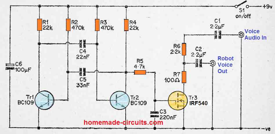
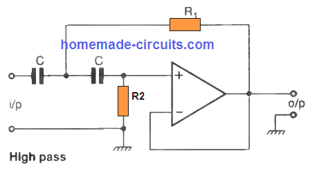
Slowing down the rise time of the modulation signal produces a somewhat better output audio, and this is accomplished by inserting a simple R/C low pass filter (R5 and C3) between the astable output and the Tr3 gate.
Tr3 is implemented in a standard VCA that also includes R6 and R7.
C1 and C2 serve as DC blocking capacitors, while C6 serves as a supply decoupling capacitor.
The circuit has the effect of modifying the input voice signals to two degrees of attenuation, the highest of which is approximately 26 dB greater than the lower, which results in the production of the robot like manipulated sound.
The modulation oscillator “breaks up” the signal by switching it between these two levels with a frequency of many Hertz, giving the desired robotic voice effect.
Despite the fact that this circuit employs the most commonly adopted technique of electronically creating a computer-generated voice effect, it performs admirably in practical use.
The input signal level can be as high as a few volts peak to peak without causing any overloading issues. S1 controls the on/off switch. The circuit draws around 1 milliampere of current.
You will need an audio amplifier unit hooked up with the output of the circuit for hearing the robot voice loudly over a loudspeaker.


Questions & Answers
What’s The second one you plugged it into in the video?
There’s no video in the above article?
Nice project!!! I watched your YouTube video and you show a modification in the circuit that generates a second robot effect. Can you please share the complete diagram of the modified circuit? I’ve been looking for that effect for a long time. It sounds like the one Princess Leia uses when she wears a mask in the beginning of The Return of the Jedi.
Hi Thanks, However Sorry I don’t have any video posted related to the above article.
Oh, sorry. I found a video on YouTube with a link in the description that points to this article and I assumed the video was yours. My mistake. Anyway, thanks for your reply.
OK, no problems.
I made this circuit, but couldn’t get it to work. I looked it over and it is exactly as the diagram but with the exceptions TR1 and TR2 are BC109C and TR3 is a BS170. Audio IN is the same as audio OUT. I’m not sure where I went wrong.
Is the oscillator working correctly? Please check the astable multivibraotor and make sure it is generating the required frequency at the gate of the FET. You can also try replacing the FET with an ordinary BJT such as BC547 and check the response
I will test the BC109 transistors to see if they work. In the mean time I was able to get something similar by changing the TR1 and TR2 to BC547, R1 and R4 to 2.2K, R2 and R3 to 10K, C4 to 10uF, and C5 to 1uF. (Very similar to the “giggle generator” from your laughter sound simulator circuit.)
OK thanks, that sounds interesting, I think with a few more such tweaks you might be able to succeed in getting the robot sound.
I was able to get the bc109 transistors to work with the circuit but only after reducing the resistance of R1 through R4.
R1,R4 = 18k
R2,R3 = 390k
I am glad you could make it work, appreciate your efforts, hope the readers will find it useful.
You can try BC547 also.
Interesting and easy to build project.
Hello Mr. Swagatam. Please does homamade-circuits have any WhatsApp group?
Hi Safiyan, sorry we don’t have a whatsapp group at this moment.