• Skip to main content
  • Skip to primary sidebar

Homemade Circuit Projects

Get free circuit help 24/7

New Projects | Privacy Policy | About us | Contact | Disclaimer | Copyright | Videos | Circuits for Beginners | Basic Circuits | Hobby Projects | Transistor Circuits | LED Drivers 

You are here: Home / Sensors and Detectors / Tilt Sensor Switch Circuit

Tilt Sensor Switch Circuit

Last Updated on June 14, 2019 by Swagatam 4 Comments

caution electricity can be dangerous

The articles presents a simple water triggered switch which is effectively implemented as a super simple tilt sensor circuit. Let's know more.

Easy to Build Circuit

Ready availability of cost effective components can be deployed to fabricate tilt sensor alarm in ultra transistor based simple circuit.

The domestic version of tilt sensor explained here is just a simple small glass or poly bottle comprising two metallic needles penetrated through its lid containing a negligible measure of water.

One can even try through one’s own innovations to develop a tilt sensor with just a 9V alkaline battery to power the entire circuit.

Circuit Operation

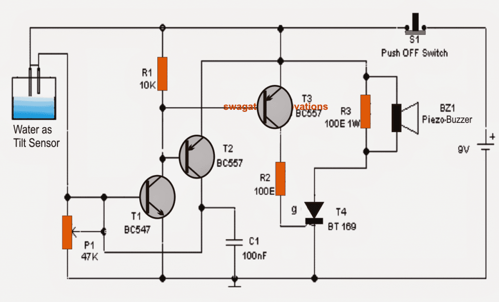
Referring to the simple tilt sensor circuit diagram below, transistor T1 is generally in dormant state and on tilting the water filled sensor assembly, the needles within the sensor container are subjected to a short-circuit caused by water with the availability of positive voltage at T1’s lower part triggering to get activated. T1’s activation triggers those of T2 and T3.

The next transistors stage which T2 provides static bias for T1 making it to be latched with T3 triggering T4 SCR which in turn powers the active piezo-sounder (BZ1). The activation once complete, the circuit can be neutralized using power push-off switch S1.

How to Setup the Circuit

For adjusting the sensitivity of circuit, preset P1 is compulsorily integrated which may be necessary if a different readily available tilt sensor is used.

In the same way, SCR(T4) besides piezo sounder (BZ1)can also be substituted with close comparable parts. Resistor R3 Resistor R3 (100-150 Ohm) is not compulsory.

Circuit Diagram

Another Tilt switch Circuit

The above design could be much simplified as given below:

tilt switch alarm for motorcycle protection against thieves

Using Tilt Sensor for Protecting a Motorcycle

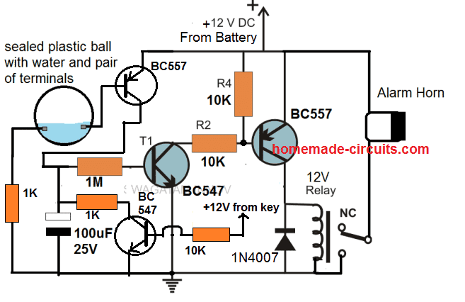
The two blue transistors along with the 100uF capacitor and the 1M resistor form a simple delay OFF timer circuit.

A water based sensor can be seen inside a sealed plastic ball with two metal terminals immersed around the surface of the water. The terminals are positioned in such a way that a slight tilt of the ball removes the water contact from one of the terminals.

When the motorcycle is on stand, the ball remains tilted breaking the water contact between the terminals.

However, if the bike is removed from the stand and attempt is made to start it, the water inside the ball is disturbed allowing an electrical contact between the terminals.

As soon as this happens, the upper BC557 is instantly activated which in turn actuates the blue transistors raising the alarm.

The 100uF capacitor ensures that the alarm does not stop for a few seconds even after the vehicle is restored to its original tilted position.

The lower BC547 is linked with a supply from the ignition key, which means that while the bike is running or active, the entire circuits remains disabled. It is enabled only when the key is removed or unlocked.

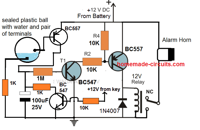
For Preventing Car Theft

For preventing car theft, the above design could be modified as shown below:

car theft protection tilt sensor application

You'll also like:

  • 1.  Simple PIR LED Lamp Circuit
  • 2.  Simple Battery Voltage Monitor Circuits
  • 3.  Barometric Pressure Sensor Circuit – Working and Interfacing Details
  • 4.  Microwave Sensor or a Doppler Sensor Circuit
  • 5.  How to Make a Simple Metal Detector Circuit
  • 6.  Simple Water Level Indicator Circuits (with Images)

About Swagatam

I am an electronic engineer (dipIETE ), hobbyist, inventor, schematic/PCB designer, manufacturer. I am also the founder of the website: https://www.homemade-circuits.com/, where I love sharing my innovative circuit ideas and tutorials.
If you have any circuit related query, you may interact through comments, I'll be most happy to help!

Reader Interactions

Comments

    Have Questions? Please post your comments below for quick replies! Comments should be related to the above artcile Cancel reply

    Your email address will not be published. Required fields are marked *

  1. Avi says

    January 26, 2019

    Thanks for reply
    I’ll be waiting for the update.

    Reply
    • Swagatam says

      January 26, 2019

      I have updated the new design

      Reply
  2. Avi says

    January 26, 2019

    Hi
    I’m learning a lot from your articles, its just amazing.
    Sir i want to make this tilt switch circuit for my bike. As any burglar tries to stole the vehicle, as soon as bike is tilted upright(90%) it triggers the alarm. But to turn on and off the circuit where should should i place the switch discreetly so that no know about it.
    Is it possible to attach the switch with handlebar lock. When the bike handlebar is locked it will turn on the circuit.

    Reply
    • Swagatam says

      January 26, 2019

      Thanks Avi, I am glad my circuits are helping you to learn. Please do not build this circuit, because this was contributed by somebody else, and it may have issues.

      I’ll try to update a new better diagram by tomorrow which you can surely try

      Reply

Primary Sidebar

Calculators

  • 3-Phase Power (15)
  • 324 IC Circuits (19)
  • 4017 IC Circuits (52)
  • 4060 IC Circuits (25)
  • 555 IC Circuits (98)
  • 741 IC Circuits (19)
  • Arduino Engineering Projects (83)
  • Audio and Amplifier Projects (114)
  • Battery Chargers (82)
  • Car and Motorcycle (94)
  • Datasheets (46)
  • Decorative Lighting (Diwali, Christmas) (33)
  • Electronic Components (100)
  • Electronic Devices and Circuit Theory (36)
  • Electronics Tutorial (116)
  • Fish Aquarium (5)
  • Free Energy (34)
  • Fun Projects (13)
  • GSM Projects (9)
  • Health Related (20)
  • Heater Controllers (29)
  • Home Electrical Circuits (102)
  • How to Articles (20)
  • Incubator Related (6)
  • Industrial Electronics (28)
  • Infrared (IR) (40)
  • Inverter Circuits (98)
  • Laser Projects (12)
  • LED and Light Effect (93)
  • LM317/LM338 (21)
  • LM3915 IC (25)
  • Meters and Testers (65)
  • Mini Projects (148)
  • Motor Controller (67)
  • MPPT (7)
  • Oscillator Circuits (26)
  • PIR (Passive Infrared) (8)
  • Power Electronics (34)
  • Power Supply Circuits (77)
  • Radio Circuits (10)
  • Remote Control (48)
  • Security and Alarm (61)
  • Sensors and Detectors (120)
  • SG3525 IC (5)
  • Simple Circuits (75)
  • SMPS (29)
  • Solar Controllers (60)
  • Timer and Delay Relay (53)
  • TL494 IC (5)
  • Transformerless Power Supply (8)
  • Transmitter Circuits (40)
  • Ultrasonic Projects (16)
  • Water Level Controller (45)

Calculators

  • AWG to Millimeter Converter
  • Battery Back up Time Calculator
  • Capacitance Reactance Calculator
  • IC 555 Astable Calculator
  • IC 555 Monostable Calculator
  • Inductance Calculator
  • LC Resonance Calculator
  • LM317, LM338, LM396 Calculator
  • Ohm’s Law Calculator
  • Phase Angle Phase Shift Calculator
  • Power Factor (PF) Calculator
  • Reactance Calculator
  • Small Signal Transistor(BJT) and Diode Quick Datasheet
  • Transistor Astable Calculator
  • Transistor base Resistor Calculator
  • Voltage Divider Calculator
  • Wire Current Calculator
  • Zener Diode Calculator

© 2023 · Swagatam Innovations