Let us look in how this entire interactive UPS and PWM voltage stabilizer works from start to finish stage by stage, just as if we are tracing it together on workbench.
Whole idea behind this design is to keep your output locked in a steady 220V AC without using clunky relays or slow motorized variacs and at same time give you instant battery backup the moment the mains power goes out.
To do that the system is split into three main blocks that work together: a mains synchronized SPWM controller, an H bridge power stage with an autotransformer and phase inverting transistors and a standby 12V to 330V DC boost converter.
Stage 1: Mains-Synchronized 555 SPWM Controller
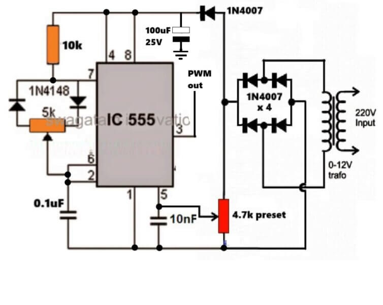
Let us start with the brain of the stabilizer which is 555 SPWM generator stage.
Here we have a standard 555 timer wired as an astable oscillator using a 0. 1uF timing capacitor, 10k resistor, a 5k preset and a pair of 1N4148 diodes to separate the charge and discharge paths.
Normally a 555 just puts out a fixed square wave, right? To turn it into a sinusoidal PWM generator that tracks the AC mains, we take a small 0 to 12V step down transformer connected to 220V input and rectify its output using four 1N4007 diodes.
Notice that there is no big filter capacitor after this bridge so we get raw, pulsating DC wave that rises and falls right along with 50Hz or 60Hz AC sine wave. We feed this pulsating signal through a 4. 7k preset and a small 10nF capacitor straight away into pin 5 of 555 timer.
Because pin 5 controls internal voltage thresholds of the 555, that incoming rectified wave continuously shifts the threshold up and down in rhythm with mains.
As a result, the pulses coming out of pin 3 automatically stretch wider when the mains voltage dips and narrow down when mains voltage rises then.
Stage 2: H-Bridge Power Stage, BJT Phase Inverter, and Autotransformer
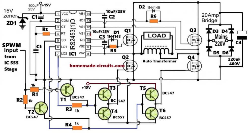
Now that SPWM signal from pin 3 travels over to the main H bridge power stage. Now the H bridge itself is built using four MOSFETs, Q1 through Q4, driven by an IRS2453D high and low side driver IC along with its bootstrap capacitors and 1N4148 diodes.
During normal operation, 220V AC mains is rectified by a 20 amp bridge and smoothed by a 220uF 400V capacitor, putting roughly 310V DC across the H bridge bus.
The output of this H bridge feeds primary winding of an autotransformer, while secondary winding of that autotransformer sits straight away in series between the AC mains and your load. Here is where the magic of buck and boost regulation happens.
Look at the cluster of BC547 and BC557 transistors, T1 through T6, sitting below the driver IC. T1 and T2 act as a controlled phase inverter, while T3, T4, T5 and T6 form push pull emitter follower buffers to give clean, fast switching edges to the low side drive.
When the mains voltage drops below 220V, then sensing circuit lets the SPWM signal pass through in phase so the autotransformer adds voltage in series with mains and boosts the output back up to 220V.
On other hand, if mains voltage surges above 220V, then the sensing circuit triggers T1 and T2 to flip SPWM signal by 180 degrees.
That phase inversion reverses the polarity of the voltage across the autotransformer so it now subtracts excess voltage from the line, holding your load right in 220V.
Stage 3: 12V to 330V DC Boost Converter for Backup Mode
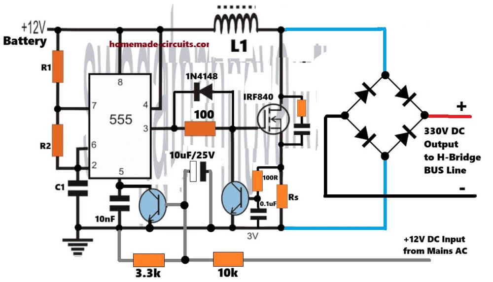
Finally, what happens if AC mains fails completely then? That brings us to the third stage, 12V to 330V DC boost converter.
In this circuit, another 555 timer drives an IRF840 MOSFET through a 100 ohm resistor and a 1N4148 turn off diode, switching a 12V battery through inductor L1. Every time MOSFET switches off, collapsing magnetic field in L1 creates high voltage flyback pulses that get rectified by a fast diode bridge into 330V DC with a small sense resistor Rs at the MOSFET source protecting it against overcurrent.
While mains power is normal, a 12V DC signal taken from the mains feeds through 10k and 3. 3k resistors to turn on an NPN transistor connected to pin 5 of this boost 555 timer. That transistor holds pin 5 pulled straight to ground which completely shuts down 555 oscillator so the boost converter stays off and does not drain your battery.
Exact moment the mains fails, that 12V sensing voltage vanishes, transistor turns off and pin 5 is released from ground.
Instantly, 555 starts oscillating, the 330V DC output from the boost converter takes the place of the missing 310V rectified mains on the H bridge bus and your load keeps running without any interruption.
How to Wind L1
To get the complete details regarding how to wind the L1, please refer to the following post:
Troubleshooting Tips
When you build a multi stage high voltage power circuit like this on bench, then you never want to power everything up at after.
Test each stage individually first so you do not blow your MOSFETs if a single trace is wrong then. Start by isolating and testing the 12V to 330V boost converter all by itself before connecting it to H bridge bus.
Disconnect the 12V mains present sensing wire so pin 5 stays released, hook up a current limited 12V bench supply and check output of fast diode bridge. If you see zero volts or the IRF840 gets hot right away then check your gate drive waveform in pin 3 of 555 and verify that your output bridge uses genuine ultrafast diodes like UF4007 or HER308. Standard 1N4007 diodes will overheat and short out almost instantly at switching frequencies above a few kilohertz.
If boost stage refuses to oscillate even when mains is disconnected, then measure the voltage right in pin 5 of boost 555 timer. If pin 5 is stuck near zero volts, then your clamping NPN transistor might be shorted collector to emitter, or residual charge in filter capacitor on the 12V mains sensing line is keeping transistor biased on.
Reducing any filter capacitor value on that sensing line will make pin 5 release much faster when the power cuts out then.
Next, check the 555 SPWM stage on an oscilloscope with a low voltage 12V AC supply feeding sensing bridge.
Look at pin 5 first you should see a clean, unsmoothed 100Hz or 120Hz half sine ripple sitting there. If you accidentally placed a large electrolytic capacitor across the sensing bridge output, then the ripple will flatten out into pure DC and you will lose your sinusoidal PWM modulation completely.
Before applying 220V mains to the H bridge, power only the +15V control rail for IRS2453D driver IC and the BC547/BC557 transistor network.
Probe the gates of Q1 through Q4 to confirm clean, crisp square waves with proper dead time. If gate waveforms look rounded or sluggish, then double check the orientation of the BC547 (NPN) and BC557 (PNP) pairs in push pull buffers because swapping an NPN and PNP transistor is very common assembly mistake that kills switching speed and causes MOSFETs to overheat.
Finally, when testing the autotransformer buck and boost action, then use a variac on the input and a 100W incandescent bulb as dummy load.
If output voltage shoots up even higher during an overvoltage test instead of dropping down to 220V, then your autotransformer winding phase is reversed.
Just swap the two leads of the autotransformer primary winding connected to the H bridge output to flip buck and boost polarity.
Frequently Asked Questions
Why is there no large smoothing capacitor after the 1N4007 bridge rectifier in the SPWM controller stage?
That bridge rectifier is only there to sense the shape and amplitude of the incoming AC sine wave, not to power a DC load.
By leaving out a large filter capacitor, pulsating DC ripple follows the exact rise and fall of mains voltage and feeds that shape into pin 5 of 555 timer which is what creates the sinusoidal PWM modulation.
Can I use standard 1N4007 diodes for the 330V bridge rectifier at the output of the 12V boost converter?
No, 1N4007 diodes are slow recovery rectifiers meant only for 50Hz or 60Hz mains frequencies. In boost converter, inductor L1 switches at high frequency so you must use ultrafast recovery diodes such as UF4007, HER308, or FR307 to rectify the flyback pulses cleanly without reverse recovery losses and overheating.
How does the circuit prevent the 330V boost converter and the 310V rectified mains from fighting each other?
While normal AC mains is present, the 12V mains taken sensing line keeps the clamping transistor switched on, holding pin 5 of the boost 555 timer grounded so boost oscillator is completely shut off. In addition, fast diode bridge at the boost output acts as a one way valve blocking 310V rectified mains from feeding backward into the IRF840 drain and 12V battery.
What happens if the autotransformer saturates or gets too hot during operation?
Core saturation usually happens if the 555 carrier frequency is set too low for the size of your transformer core or if there is a DC imbalance in the H bridge drive then. Make sure 5k preset and 10k resistor on SPWM 555 timer are adjusted to high enough switching frequency typically around 15kHz to 20kHz and check that both halves of the H bridge are switching symmetrically.
How do I calibrate the exact 220V output regulation threshold?
Connect a variable AC source (variac) to the input and set it to a slightly low voltage like 190V AC. Adjust the 4.7k preset feeding pin 5 of the SPWM 555 timer until the output across your load reads a steady 220V AC. Once that is locked in, slowly raise the variac past 220V up to 250V to verify that the BJT phase-inverter stage flips polarity and holds the load voltage steady.

Need Help? Please Leave a Comment! We value your input—Kindly keep it relevant to the above topic!