A simple, cheap yet highly effective infrared remote control safe lock circuit can be studied in the following post.
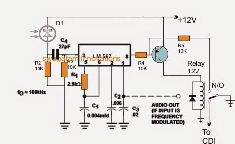
Using IC LM567
The LM567 IC is one of my favorites simply because it's too versatile, and becomes applicable in most of the crucial circuit concepts through hassle free configurations.
One such crucial yet simple IR remote control receiver application can be seen in the above diagram, which activates only through a unique predetermined frequency as set by R1/C1 in the circuit.
The above concept can be used in automotive security applications for locking the safe/vault through a uniquely set frequency code.
In the shown circuit R1/C1 determines the latching frequency of the unit, which may be calculated using the following formula:
f = 1/R1C1, which constitutes to be 100kHz for the shown values of R1, C1.
Pin3 which is the receptor pinout of the IC is configured with a IR diode for receiving an incoming tone locked frequency set at the matching 100kHz frequency.
How it Works
When such a matching frequency is detected at pin3 of the IC, pin8 responds and becomes low momentarily activating the transistor latch.
The transistor and relay latch together to acknowledge the response and open the safe lock for the user.
Any other frequency which may not coincide with the set R1/C1 value is simply rejected by the IC keeping the vault secured and locked, thus the system becomes extremely foolproof and safe from potential bike thieves.
pin1 output from the IC can be configured with an audio amplifier and buzzer in case an audio signal is felt essential during the remote control activation.
However this may require the transmitter to be equipped with a modulated audio signal over the carrier base frequency.
A very simple complementing IR remote handset circuit may be seen below:
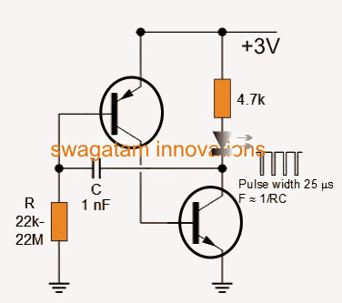
It's a simple two transistor R/C based oscillator, whose frequency is determined by the shown R and C values and coincidentally here too the formula is identical to its Rx counterpart, that is:
f = 1/RC
Thus the Tx circuit frequency becomes much easier to calculate and match with the LM567 receiver circuit discussed in the previous section.
For activating the Rx circuit, the above Tx circuit IR diode emission simply needs to be focused on the IR receiver diode of the Rx unit. This instantly unlocks the Rx circuit for the intended results.
The infrared remote control security lock circuit can be used for locking a multitude of other security devices which require a foolproof uniquely coded locking operations.



Questions & Answers
The 567 IC doesn't need any power to operate ?
pin4 is (+) an dpin7 is (-), these should be connected to the respective rails.
Hi Swagatam, great to see your circuits, they are very impressive. I am not sure if this is the right place to request this but I am looking for a secure RF remote which cannot be copied (easily). I could not find anything on the internet except some suggestions to use Keyloq – but how , couldn't figure that out. I am an electronics hobbyist so if you give some ideas I will be able to carry it forward.
Thanks Vijay, You can perhaps buy it ready made either from the market or from an online store.
The following article will help you to get an idea of the product that I am referring to:
https://www.homemade-circuits.com/2012/08/how-to-buy-and-use-rf-remote-control.html
Hi, sorry but I am past that stage. I have already bought these and am able to control them using Arduino. I am also working on making it available via the internet. All that is cake, what I am looking for is to make this secure. At present as I have hacked this remote and simulated the same signals, any other person can also do that and would be able to control my house (provided he is near enough). I want to make this communication secure so that I can avoid that. Even if I have to build the entire thing for that – I am game for that. The only thing is that I have not been able to get any ideas of how to make it secure. The only thing I got was that car remotes also use the Keyloq algo where each code generated is unique and hence difficult to predict for hackers. Couldn't get enough info on the algo and the way to implement it.
I thought these had built in code-hop technology, if not you can try the following two options:
http://www.radiometrix.com/files/additional/ktx2.pdf
ww1.microchip.com/downloads/en/DeviceDoc/40158e.pdf
Great! that helps. I'll try these out. Thanks for the direction.
you are welcome!
hi friend s I am learner. I want material like pcb, ldr, ic s etc. where I get all the stuff to do.
please tell me on watsapp : 9494989482.
Shekhar, there are many online stores such as digikey, mouser, vegakit, onsemi from where you can get the required parts through courier and COD payment
Hi. Thanks for sharing this up. I need to know which are the capacitors values. The one that comes from pin 2 and the other connected to the pin 6. Thanks!
6nF at pin2 and 4nF at pin6
which npn & pnp transistors(numbers) are used in ir remote headset
you can use a BC547/BC557 or any other similar
I want the appartus required for infrared-remote-control-security lock
Hello,
Are you sure the resistor in the collector of the NPN transistor of the oscillator is 4.7KOhm or the supply voltage is 3V? The IR LED will not give off too much light. I am afraid that circuit will not work as expected. Usually, a few mA are needed. I think, there must be a typo somewhere.
Hi, thanks, you are right, it should be reduced to 100 ohms or even less. However using 3V shouldn’t be an issue.
Hello Swag,
please guide how can we measure frequency of transmitter circuit shown above.
Hi Sachin,
You can measure the threshold frequency across the capacitor C1..