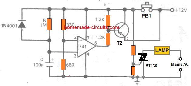
A simple automatic bedroom lamp timer circuit has been described here to switch off your bedroom lamp after a fixed predetermined time. The use of the reliable 741 IC makes the circuit very easy to build and moreover very accurate.
Introduction
The circuit of an automatic bedroom lamp timer presented here is super easy to understand and uses very few components to operate.
The use of an integrated circuit 741 makes the circuit more accurate compared to the transistor ones.
In many houses, the light switch sometimes is situated at a distance from the bed and often, folks may have the habit of reading a book or so before dozing off.
In such an occasion one would desire they had a device that could be timed as required to automatically switch-off the light after a certain fixed period.
The proposed circuit of a bedroom lamp timer is designed exactly to satisfy the above need.
The device will automatically switch off the connected bedroom light and itself after a particular period of time depending upon the setting.
A standard RC timing configuration has been employed and works satisfactorily for the present application.
The IC 741 which is wired as a monostable multivibrator forms the main active part of the circuit.
You already must be too familiar with this IC and we know that it’s basically an op-amp having huge applications in electronic circuit configurations.
In one of the standard applications the IC 741 may be used to compare voltages in between its inverting and non inverting inputs.
On sensing the trigger threshold at one of its inputs, the IC toggles its output condition and activates the output parameters
Here as explained above, it is used as a comparator and is used to compare the charging voltage of a capacitor to a particular set level after which it switches the output.
Circuit Operation
Parts List
- Resistors are 1/4 watt 5% CFR
- 1M, 330Ω, 680Ω = 1 each
- 1.2k = 4
- Capacitor Electrolytic C 100µF / 25 V = 1
- Triac BT136 = 1
- Push button = 1
- 12V DC power supply = 1
Referring to the figure, we see that the inverting input is set to about 2/3 rd of the supply voltage. This voltage level in fact becomes the reference source to the IC.
The non inverting input pin of the IC is connected to the unction of a RC network, where the other end of the resistor R (variable if required) is connected to the positive supply and the negative pin of the capacitor C goes to the ground point of the circuit.
Powering the circuit is rather done in an interesting manner. Here the transistor T2 along with PB1 is so wired that on pressing PB1, T2 latches and holds the supply voltage to keep the circuit powered.
Now, initially the voltage at pin #3 is almost at the ground potential because of C, however as C charges the potential at this pin of the IC starts rising.
Depending upon the value of R, after a particular length of time C charges itself to a level which may be above 2/3 rd of the supply voltage as set at the inverting input.
The IC responds and immediately toggles its output to produce a logic high or a positive voltage.
T1 and the triac at the output deactivates and switches of the external load connected to it.
The high logic at the output of the IC also inhibits T2 from conducting and breaks the latch to switch of the whole system.
The timing sequence of this bedroom lamp timer can be repeated or initiated by pressing PB1 whenever felt necessary.
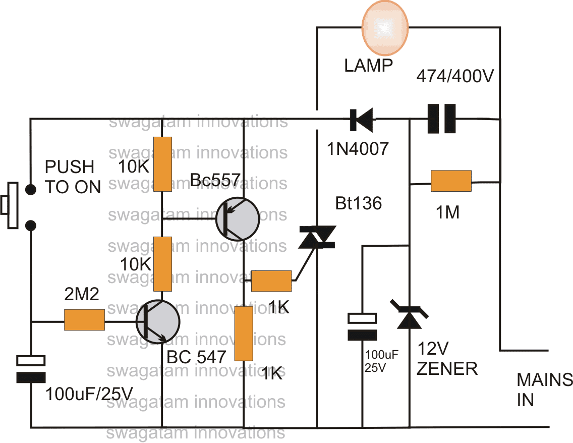
Using Transistors
The simple automatic bedroom lamp timer circuit can be also implemented using a couple of BJTs as shown in the following diagram.
The idea looks even more compact due to the inclusion of a transformerless power supply.
The two BJTs are wired like a delay OFF timer stage.
As soon as the push button is pressed, the 100 uF capacitor is fully charged, and the transistors become activated, switching ON the triac and the bedroom lamp.
On releasing the push button the transistor and the triac along with the lamp continue to remain switched ON due to the presence of the stored charged inside the 100 uF capacitor, which holds the BJTs base forward biased.
However, the capacitor now also starts discharging though the 2M2 resistor and the NPN emitter pin.
When the voltage across the capacitor drops sufficiently below the holding level of the NPN, the transistors are unable to remain switched ON anymore and are switched OFF, turning off the triac the lamp.
The time for which the lamp can stay ON, is basically determined by the 100 uF capacitor and the 2M2 resistors.
WARNING: All the circuit concepts presented above are not isolated from the mains AC, and therefore touching the elements in the powered condition can be fatal. Necessary precautions are strictly advised.
Make sure to use a plastic enclosure for the circuit once the working of the finalized design is confirmed.


Comments
Sir can you please explain me how to set a time in Simple bedroom lamp and how it works …. please sir kindly give me the solution
Saranya, when push button is pressed, the 100uF charges and slowly discharges through the 2M2 resistor, this causes the transistor to conduct and switch ON the triac and the lamp. When the capacitor is fully discharged, the transistors stop conducting and the triac switches OF with the lamp.
You can adjust the 100uF capacitor and the 2M2 resistor to different values to get different delay OFF times on the lamp
Thank You so much Sir!
You are welcome Saranya!
I have been following you for some now but I can not find daics or any substitute
Dear Mr. Swagatam
I hope you are fine and healthy. I would like to inform you of another problem in below link.
Please let the visitors of your interesting site to see the content of tile “Voltage regulator circuits using transistor and Zener Diode”. it seems have been locked.
https://www.homemade-circuits.com/?s=1.5+volt+output+power+supply
best regards
Nassim
Thank you Dear Nassim, The link is working fine for me, you can check it here:
Voltage Regulator Circuits using Transistor and Zener Diode
Thank you so much dear Swagatam
truly yours
nassime sabaa
Dear Mr Swagatam
referring my few ours ago that I told you that I can not see the circuit ” Simple Bedroom Lamp Timer Circuit Using IC 741″ I would like to inform you that when I used tor browser from Torproject, I saw your interesting IC741 circuit board I mentioned above.
I am so astonished why Google chrome browser does not show it.
Please accept my excuse.
God bless you
Bye
Thank you Dear Nassime for your kind concerns.
Yes it is indeed strange, and difficult to understand how these different search engines actually work to judge the quality of the websites!
I Appreciate your feedback, please keep up the good work!
Please accept my warmest greetings sir
Hello
Is there any problem in this page?
I cant not see the circuit under title ” Simple Bedroom Lamp Timer Circuit Using IC 741″ .
there is a 2 transistor circuit instead.
sincerely yours
Hi, thank you very much for pointing out the missing diagram, it seems the diagram was deleted by mistake.
But No problem, I have somehow added the diagram, as per the given explanation. It should work almost like the original op amp concept
Swagatam
Hi, and greet you warmly
I have one question about the OFF-ON switch
I am looking for a simple schematic (transistors, etc.) to make it possible with one button
1) switch on the device
2 turn off the device
on the same button ,,,, bistable
I’m from Poland
andrew
I admire your devotion and dedication to people
Thank you Andrew,
You can try one of the concepts presented in the following article
https://www.homemade-circuits.com/build-these-simple-flip-flop-circuits/
HI,
plz give me timer circuit diagram for exhaust fan,it should automatically turn off after few minutes when i switch it off.
means it have to run a few more minutes after I switch it off
Try the following circuit:
https://www.homemade-circuits.com/wp-content/uploads/2012/05/delaytimerimprovedcircuit-2-1.png
replaec the push button with an ON/OFF switch
hi sir, we are having project which has the main application of diodes and i am thinking of presenting this in our class since i think it is easier and we can make this before 1 month.. so, may i ask for the components that you've been using together with the value and the value of the power supply that is needed to work this on.
Please… Thank you in advance.
really need your quick reply.
Hi Riclyn,
the last circuit is although not entirely diode based, you can make it if you wish to.
All the the parts info is printed in the diagram itself, please note it down on a paper and procure the parts for assembly.