Learn a super simple procedure to make a weighing scale meter circuit useful for measuring smaller magnitudes of weight.
The Concept
The concept is very simple, a light beam is allowed to pass through a linearly colored ribbon and fall over an LDR.
The color shade of the ribbon positioned in front of the light source at any instant will depend on the weight placed over a spring loaded mechanism.
The corresponding change in the light level is converted into a corresponding difference in the resistance of the LDR which is ultimately read over an Ohmmeter and the equivalent weight is determined.
A digital weighing scale is an indispensable device as far as determining smaller magnitude of weights is concerned. However these gadgets can be too sophisticated and expensive to procure.
A simple design idea of an analogue weighing scale meter circuit presented here promises to be equally accurate yet very cheap.
We all have seen this machine very commonly used with most of the shopkeeper and retailers.
It is used for determining the weights of the various materials being sold to the customers so that the items may be correctly rated as per the displayed weight over the machine.
This incredible device is able to detect even the minutest magnitude of weight placed over it and accurately displays it over a digital scale.
Yes we are discussing weighing scales normally used for weighing smaller weights ranging from probably mgs up to a few kgs.
Simple Weighing Sale Design vs Commercial Design
The commercially available weighing scales are rather too sophisticated, accurate and therefore very costly too.
The design of a simple electronic analogue weighing scale meter circuit presented here has been devised by me and is pretty accurate, very low cost and can be constructed even by a layman.
The idea is simple – a linearly colored semi-transparent ribbon is made to move or dip in response to the pressing weight, a light beam from a light source is allowed to pass through this ribbon and fall over an LDR.
The LDR is connected across an Ohm meter, so, as the weight pushes the ribbon, it slides down and settles at a particular point and offers a particular corresponding shade in front of the light source.
The light intensity is optimized according to the darkness or lightness of this shade and the LDR reads the proportionate light intensity level and directs it to the meter so that it may be directly read over its calibrated dial.
How the Weighing Scale Circuit is Designed to Work
Let’s try to understand the actual functioning of the designed prototype:
Parts List
- White LED 5 mm, 20 mA = 1
- Small LDR = 1
- Calculated Spring mechanism and cabinet = 1
- 3 V Cell Li-ion = 1
- Moving Coil Ohm meter = 1
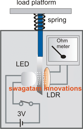
Referring to the homemade weighing scale meter circuit above, we see that the arrangement is pretty straight forward.
A central pillar or shaft which forms the main and the sole moving part of the system passes through an appropriately sized hole made over the top surface of the cabinet.
The external end of this rod terminates into a flat platform which forms the base for keeping the weights under question.
The rod and the platform are held in a rigid posture by a spring positioned in between the platform and the cabinet top surface.
The shaft actually passes through this spring.
The spring is required so that the weights are properly optimized and the level of the platform returns to its original position once the weight is removed.
A linearly colored or darkened translucent ribbon which forms the heart of the entire mechanism is connected to the inner end of the above movable shaft.
Also a white LED (used as a light source) and an LDR (light receiving component) are positioned exactly opposite, facing each other and partitioned by the ribbon.
An analogue moving coil type meter configured as an Ohm meter or a resistance meter is integrated with the LDR.
The LED is powered through a cell and is switched ON when in use.
The light beam produced from the LED passes through the ribbon and falls over the LDR and a corresponding value is displayed over the meter depending upon the opacity of the ribbon.
When there’s no weight placed over the platform, the spring mechanism keeps the shaft in a position that produces the darkest shade from the ribbon in the path of the LED beam and therefore the meter also reads a minimum or zero value over its calibration.
The moment a weight on this weighing scale is placed, the shaft dips proportionately and the ribbon slides down to produce a linearly changing shade in front of the LED light beam and finally settles down to a corresponding lighter shade level.
The operation is instantly translated over the meter to provide the equivalent value of the weight being measured.
Simplifying the Weighing Machine even Further
In the above example it is clearly evident that the main weighing scale element is the spring, and a spring can be considered pretty accurate and long lasting compared to any other form of compression based sensor.
Therefore if a good quality spring is used we can assume the output to be extremely accurate and consistent throughout its life.
Based on the above consideration we can go a step ahead and make the above LDR LED based design even more simpler, as shown below.
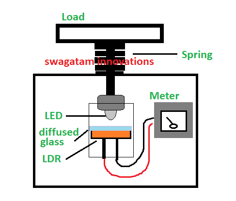
In the figure above, we can see a spring mechanism system fixed over a box, the weighing surface fixed over the spring, and the central spindle of the load surface going inside the box, and terminating into a LED point.
The LED may be powered with an external 3V supply from a DC power supply source connected through flexible wires.
Under the LED we can see an LDR positioned such that the LED can move closer or farther away from this LDR depending on the spring tension or the variation levels on the spring causes by the load.
The LDR wires are interfaced with a suitably calibrated Ohmmeter.
How this Weighing Scale Works
The concept looks pretty obvious and clear, and is quite self explanatory.
With no load on the weighing surface, the spring pulls the LED upwards away from the LDR at a maximum possible distance, which causes minimum incident light on the LDR surface. This low light level is shown as almost zero on the Ohm meter.
Once a load is kept on the weighing surface, depending on the weight of the load the spring is depressed downward causing the LED to move closer to the LDR at a specified positioned.
This causes the LDR to change its resistance proportionately, which can be identified on the ohm meter and calculated as a direct equivalent reading for the load's weight.

Questions & Answers
I am thinking about the easiest way to measure weight. I draw a system very similar to your design but I realized if we place the load’s centre of gravity on the centre of the scale (exactly above the spring, it will work perfectly but if the centre of gravity deviates from the centre of the scale, there will be miss reading. It will work if we use it for liquids, rice etc. Or if the load placed I’m the centre.
What do you think? I might be wrong.
Thanks for sharing
The central shaft/spring mechanism should be perfectly straight, and must not tilt when the weight is not at the center, then the reading will be accurate
Hi Mr. Swagatam
My recommendation to this design is that we can use a right angle triangular slit or shade as a shading element too; this triangle linearly passes or blocks the light beam and with a big sized photocell or solar cell as a detecting element will work well. Thanks and best regards.
OK thanks Hamidreza, however, a photocell or solar cell cell could be much costlier compared to a an LDR
Hi Swagatam,
I like your idea. It’s cheap to implement. However, from the viewpoint of an electronics engineer, I know that the accuracy of this circuit depends largely on how linearly coloured that semi transparent ribbon is. I hope you considered that in your design.
Secondly, your light source. The brightness MUST be constant all through the period of measurement.
I hope you considered that as well.
Using a constant current source to drive the LED should ensure that the brightness of the LED is very stable at an added cost anyway.
Thanks for the idea Swagatam.
Thanks Yusuf, yes all the points indicated by you will need to be considered while making this design, another element is the spring which will not be linear with its operations, so we will have to calibrate the dial through some practical tests and set the range in the dial accordingly.
Thanks. The idea is amazing.
I am glad you liked it!!
I need circuit diagram of weighing scale capacity of 2 ton please provide the diagram
Hello sir,
What will be the hardness of the spring and how to calibrate the system any suggestions please.
It will need to figured out with some practical experimentation depending on the selected load range….
does this idea still live? any1 make it so far? can it be used for a large amount of weigh such as a ton or two?
this idea was invented by me, and the design looks logical and technically correct and therefore would definitely work, even for the big loads,…..only the meter dial will need to be calibrated correctly beforehand…
super mech with ece
Any circuit diagram so far ??
thanks mate!
how the resistance change is converted to equivalent weight
pls mail me on my email kiran.akkalkotkar@gmail.com
I have explained the whole operation in the article, please find it there.