In the following content I have explained two simple 12V, 1 Amp switch mode power supply (SMPS) circuit using the very reliable VIPerXX IC from ST microelectronics.
With the advent of modern ICs and circuits, the age old iron transformer type of power supply are surely becoming obsolete.
Today power supplies are much compact, smaller and efficient with their functioning. Here I have explained one outstanding switch mode power supply circuit which can be easily built at home for deriving clean, ripple free 12 V DC.
Thanks to ST Microelectronics IC, the VIPer22A, which has made the construction of truly efficient and compact SMPS power supply unit possible that too by using a very few number of electronic parts.
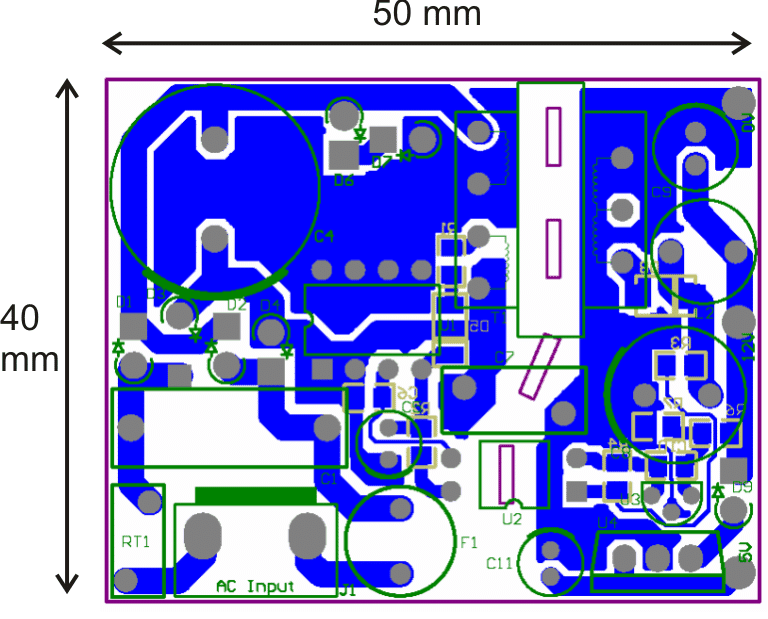
As can be seen in the picture, the circuit is indeed very small, compared to the power that is available from it. It's just 50 by 40 mm in its dimensions.
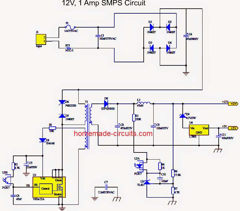
The circuit diagram is very easy to understand, let's study it with the following points:
1) SMPS using VIPer22A
Looking at the figure we can easily see that the configuration does not involve too many stages or parts.
The input mains AC, as usual is first rectified using ordinary 1N4007 diodes which is fixed in the bridge network mode.
The rectified high voltage DC is filtered using the high voltage capacitor.
The next stage is the crucial one which incorporates the outstanding chip VIPer22A manufactured by ST Microelectronics.
The IC alone functions as the oscillator and induces a frequency of around 100 KHz into the primary winding of the ferrite E core transformer.
The IC is absolutely rugged and is internally protected from sudden voltage in rush and other voltage related component hazards.
The IC also incorporates built in over heat protection which makes the IC virtually indestructible.
The voltage induced at the input is effectively stepped down at the output winding, due to low eddy current losses, about 1 amp current becomes available from a relatively tiny ferrite transformer.
With the coil specs shown the voltage is around 12 and the current is around 1amp.
A special feedback circuitry is also included in the circuit for maintaining high degree of protection and power saving features.
The feedback loop is implemented via an opto-coupler which becomes active during abnormal circuit conditions.
When the output voltage tends to rise beyond the set threshold the feed back loop becomes operative and feeds an error signal to the IC FB input.
The IC instantly comes into an corrective mode and switches off the input to the primary winding until the output returns to the normal range.
You may also want to read this: 24watt, 12V, 2 amp SMPS using a single IC Most recommended for you.
Circuit Diagram
PCB Layout
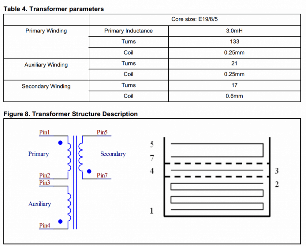
Transformer Winding Data
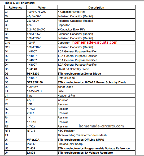
Parts List
For the original datasheet please refer to this article.
2) Another 12V 1 amp simple SMPS using IC TNY267
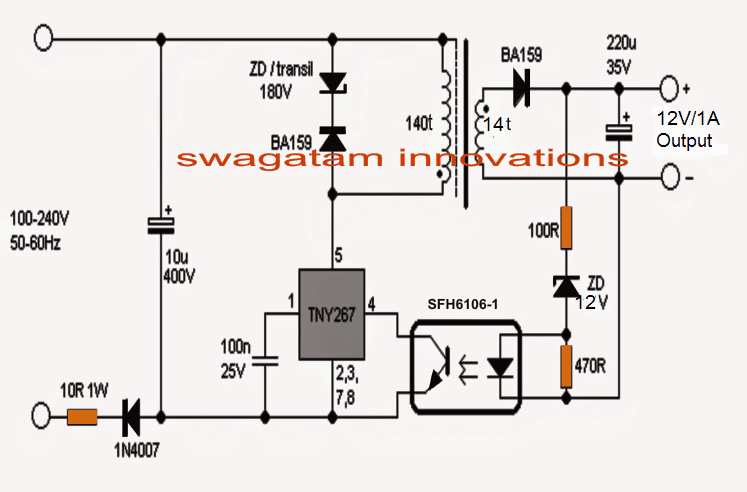
How it Works
The simple smps circuit shown above uses the popular tiny switch IC TNY267. It is a tiny mosfet based 120V to 220V switching oscillator IC which only requires configuring with a ferrite transformer and a stepped down Vdd operating voltage.
The design is so simple that a mere visualization of the schematic is enough to tell us the functioning details quickly.
The stepped down start voltage is acquired from stabilizing network using a 180V zener diodes and the fast recovery diode BA159 after rectifying the mains 220V through a 1N4007 diodes and the 10uF/400V filter capacitor.
As soon as this voltage is applied to the IC, it begins oscillating and its internal mosfet begins switching the ferrite transformer primary at the predetermined oscillating frequency.
Being a flyback design, the secondary also starts conducting during the OFF cycles of the primary through mutual induction and generates the required 12V voltage at the output side.
This voltage may not be stabilized, therefore an opto-coupler based feedback is used and the link is configured with the exclusive shut down pinout 4 of the IC.
This ensures that the output never exceeds, and remains fixed at 12V 1 amp proportion.
Transformer Winding Data
The transformer winding is actually quite straightforward, and may be done in the following manner. Keep in mind that the black dots indicate the start points of the winding which is very important, and must be strictly followed while winding the transformer.
The primary wound using 36 SWG super enameled copper wire upto 150 turns, while the secondary is wound using 26 SWG wire upto around 12 to 15 turns.
The core can be a standard E19 type ferrite core having a bobbin with central core cross section area of approximately 4.5mm by 4.5mm.

Comments
I would greatly appreciate guidance on how to build the PWM section using 13003 transistors for the typical Chinese mobile chargers commonly found in today’s market. These chargers are mostly for Android devices and can supply between 2 to 2.4 amps.
The problem I encounter is that the ICs used in these chargers’ PWM sections aren’t easily available on the Indian market. There is also a lack of datasheets or detailed documentation online that explains their pin configurations. Unfortunately, the pin layout of these ICs does not match the more commonly used PWM ICs we have, like the Viper22A, TNY268PN, AP8022, and KA/UC3842. This suggests a significant difference in the internal design of the PWM ICs used in these chargers.
Furthermore, it’s important to mention that most of these chargers do not use an opto-coupler, as they are designed with a self-feedback system. Any insights or help in dealing with this issue would be greatly appreciated.
Thanks Soumitra, You may find the following post useful to understand how an ordinary SMPS could be modified with a PWM feedback or cut-off:
https://www.homemade-circuits.com/how-to-make-variable-current-smps/
If there is no information available about the control IC used in the SMPS then you may have to manually find out the shut-down pinout of the existing IC, by grounding the different pins and finding grounding of which pinout causes the output to shut down.
Once you find it then you can integrate the feedback section as discussed in the above linked article.
Hi Swagatam, what an excellent site you have, I was looking for information about pirs initially but came across your article about PSU.
I would like to ask you regarding this topic, I was thinking instead of building a PSU why not use a ready manufactured one as their are plenty of plug in PSU rated 5v or 12v with current capacity of 2amps or perhaps more?.
I want to drive my pir from such a supply and are these plug in devices give a good direct current or a way to improve if not.
Respectively
Thomas McGhee.
Thank you so much Thomas! I am Glad you found this site interesting!
Yes, you can buy any ready-made SMPS and use it to power your PIR circuit.
All these SMPS circuits will provide a decent DC output, nevertheless, you can further improve it by adding an external 1000uF/25V capacitor across the output +/- supply lines.
Let me know if you have any difficulties with the circuit.
For a PIR related question, please feel free to post your comments under any of the following articles:
https://www.homemade-circuits.com/?s=PIR
sir, what is the default diode 1N4007
Hello Thulaseedharan, there are 5nos of 1N4007 diodes, 4 in bridge rectifier and another one at D7
hi,
where do I get the detailed design on the smps ferrite transformer with flyback topology.I searched many on the design.
Hi, you can refer to the following post:
https://www.homemade-circuits.com/how-to-design-and-calculate-ferrite-core-transformers-for-inverters/
Hi,I designed the ferrite with 12v and 10 amp output and I used to install it in a working 12v 10 amp smps that I already made with a 120 watts ferrite core.but the problem is the switching mosfet getting hot when I connect the transformer (with no load output) that I designed.but I an getting 12v output and getting output side about 2 amp current.I tried increase the load but the mosfet getting too hot so I stopped it in 2 amp load
If the MOSFET is getting hot that means the transformer is not correctly wound and is not matching with the input frequency.
hi I successfully designed a smps with flyback topology.I need some help in making it a better one.need to use short circuit protection and also over current protection could you please help me with that.I am using uc3843 ic for smps.
It can be simply done by configuring the ISENSE terminal of the IC with the MOSFET source side current limiting resistor.
Please check out the following document. All the necessary details are provided in this document:
https://www.ti.com/lit/ds/symlink/uc3843.pdf
The actual purpose of use of PC 817 opto coupler along with fixed volts zener diode and resistor voltage regulator in the SMPS system of stepping down of emf voltsges……..
What is the meaning of the SWK WORD
There’s no SWK work in the article.
Please explain the 36SWK and 26SWK Wörds
They are SWG super enameled copper wires.
What is the diameter of the wire for trasformer
You can use any online software for converting SWG to mm
Dear sir,
I want to design
please share me 12v 1A schematic for non isolated without optocoupler
Arkesh, optocoupler is a must otherwise the output will float with dangerous mains AC voltage.
Hello Swagatam!
Good evening from Nigeria.
Please I have a serious issue with this design; I have built this circuit up to 4 times and in all, they work very well without load. But anytime I connect load such as relay, the voltage drops to almost 2.5volts. and when this happens, the opto-coupler will begin to make clicking sounds; but when I removed the load, the voltage goes back to normal and the clicking sound stops.
I made another one to serve as a charger for my cordless drill machine 21volts; the smps voltage is about 24volts on no load but when the batteries are connected, the voltage drops to about 18volts and the clicking sound begins to produce again. I have tried series of options but none could solve the problem. I used EE25 and tny268P tiny switching IC.
Hello Kingsley,
If your SMPS is dropping voltage when loaded then definitely it is due to a wrongly constructed transformer. The transformer is the crucial element of these SMPS circuits, and if it is not built optimally then the performance might suffer.
Also, Try using a bifilar type of wire for the transformer. Bifilar means using a bunch of thin wires together and winding them in parallel.
I think EE25 is quite big for the above SMPS designs. As mentioned in the winding details the E core size must be E19/8/5
Thank you sir for your response. Please I want to clarify something about the transformer and I wish to ask: do I have to make the primary turns half, then the secondary before completing the second half of the primary?
If not, then I think the transformer was wound very tight and the wires are padded tightly parallel to each other. I used single strand of 36AWG wire to make the primary turns and 3 strands of the same 36AWG wire to make the secondary.
I want to note that I made the primary turns in full before making the secondary turns.
I don’t think sandwiching the secondary between the primary is absolutely necessary. Normally the primary is wound over the secondary winding with a isolating tapes in between and on top.
The secondary winding which has higher number of turns must be wound first, after winding the secondary then the primary must be wound over the secondary.
Also the EE size must be as specified in the table.
Good evening Sir,
Finally the circuit is working. There was a problem with the core Ee 19. The core was not working above 35khz . I have bought ee25 core from Amazon and the core worked well with the prescribed winding direction. The ic is getting bit heated . I have used a aluminium heat sink Sir . Thank you very much Sir .
That’s great Shantanu, I am glad you could build the circuit successfully. I hope the other readers will find it inspiring!
Thank you Sir . Sir kindly let me know the direction of the windings of primary,secondary and auxiliary coils of the transformer.
Sir can you please provide me a low-cost circuit diagram which can generate square wave frequency between 25khz to 35 khz.
Thank you Sir . Subho Navami Sir.
Hi Shantanu, the direction of the winding is shown in the transformer winding layout diagram. The black dots indicate the start of the winding, the direction of the winding are identical for all the winding.
For a square wave generator you can refer to the following article:
Square Wave Oscillator Circuits
Wish you a Subho Navami to you also
Good evening Sir. Please provide me some more details information regarding the inductor to be used for Viper22a ic . I have Ee 19 core, but the core is not gapped . What is the air gap required . Also please tell me the direction of the turns of primary, secondary and auxiliary coil of the inductor. Sir please let me know. Happy Durga Puja Sir . Also Sir please let me know your email address so that I can send you the photos related to the subject in case of difficulty. Thank you Sir.
Hi Shantanu,
You can get all the required information under the table 4 and figure8. While fixing the E cores, make sure to insert a single layer of paper or insulation tape between the E core surfaces that touch each other. This will allow the necessary gap between the cores.
Pictures actually might not help to troubleshoot an SMPS, because SMPS is a complex circuit and will need a good prior knowledge to finish it successfully by the user…
Wish you too a Happy Durga Pooja.
Bom dia irmão, posso usar este circuito para uma carga com variação rápida da corrente? Entre 450 a 900mA
Hello Marlon, current cannot be varied in this SMPS design, but you can use any load rated at 12 V and below 1 amp
Hi sir, the second proposed circuit diagram, the diode employed, was to block the ac input, but to rectify the other hand ac input, can I give it a 1n4007 diode to retify it effectually? Thanks sir, looking forward to your quick response
.
Hi Eniola, Are you referring to the BA159 diode. Since the output is a high frequency AC, only fast diodes like BA159 is recommended, however you can also try 1N4007 and check if it works.
Hi sir,the ac input line, the one with 10R1W and 1n4007, but as you can see the diode latch off the AC line input, but the other hand no retify diode,so as to power the transformer efficaciously.can I place a 1n4007 diode?
Hi John, sorry I didn’t understand what you meant by latching of AC line. The diode will not latch anything, it will only rectify the half wave cycles of the AC, which ensures a reduced surge current on the circuit, compared to full wave rectification.
Fine
Thank you for the good work. I have always admired your posts.
My question is, how do I modify this power supply to charge a 12v 7AH lead acid battery?
Hi, you can adjust R6 value to increase the output to 14.1v for charging your 12 V battery
Thank so much for your reply.
mary xmass, pls sir is there a way u can provide me a circuit that can chase away squaerr from eating up my coconut . this is the way i want it to function each time the circuit sence the present of the squerrer it will emitt sound that will chase the farm animal away. waiting for your responds.
Merry Christmas youngking, you can try the last design presented in the following article:
https://www.homemade-circuits.com/dog-barking-preventer-circuit/
Components list plzz give me
Updated….
can i use e20 core
E19 is the recommended one.
yes you can, according to me.
Can I use any TNY series IC and opto coupler in simple 12V 1A SMPS circuit?
The IC is short circuit protected according to its datasheet.