MPPT stands for maximum power point tracker, which is an electronic system designed for optimizing the varying power output from a solar panel module such that the connected battery exploits the maximum available power from the solar panel.
Introduction
NOTE: The discussed MPPT circuits in this post do not employ the conventional control methods like "Perturb and observe", "Incremental conductance, "Current sweep", "Constant voltage"......etc etc...Rather here we concentrate and try implementing a couple of basic things:
- To make sure that the input "wattage" from the solar panel is always equal to the output "wattage" reaching the load.
- The "knee voltage" is never disturbed by the load and the panel's MPPT zone is efficiently maintained.
What's Knee Voltage and Current of a Panel:
Put simply, the knee voltage is the "open circuit voltage" level of the panel, while the knee current is the "short circuit current" measure of the panel at any given instant.
If the above two are maintained as far as possible, the load could be assumed to be getting the MPPT power throughout its operation.
Before we Delve into the Proposed Designs, let's first get acquainted with some of the basic facts regarding solar battery charging
We know that the output from a solar panel is directly proportional to the degree of the incident sunlight, and also the ambient temperature. When the sun rays are perpendicular to the solar panel, it generates the maximum amount of voltage, and deteriorates as the angle shifts away from 90 degrees The atmospheric temperature around the panel also affects the efficiency of the panel, which falls with increase in the temperature.
Therefore we may conclude that when the sun rays are near to 90 degrees over the panel and when the temperature is around 30 degrees, the efficiency of the panel is toward maximum, the rate decreases as the above two parameters drift away from their rated values.
The above voltage is generally used for charging a battery, a lead acid battery, which in turn is used for operating an inverter. However just as the solar panel has its own operating criteria, the battery too is no less and offers some strict conditions for getting optimally charged.
The conditions are, the battery must be charged at relatively higher current initially which must be gradually decreased to almost zero when the battery attains a voltage 15% higher than its normal rating.
Assuming a fully discharged 12V battery, with a voltage anywhere around 11.5V, may be charged at around C/2 rate initially (C=AH of the battery), this will start filling the battery relatively quickly and will pull its voltage to may be around 13V within a couple of hours.
At this point the current should be automatically reduced to say C/5 rate, this will again help to keep the fast charging pace without damaging the battery and raise its voltage to around 13.5V within the next 1 hour.
Following the above steps, now the current may be further reduced to C/10 rate which makes sure the charging rate and the pace does not slow down.
Finally when the battery voltage reaches around 14.3V, the process may be reduced to a C/50 rate which almost stops the charging process yet restricts the charge from falling to lower levels.
The entire process charges a deep discharged battery within a span of 6 hours without affecting the life of the battery.
An MPPT is employed exactly for ensuring that the above procedure is extracted optimally from a particular solar panel.
A solar panel may be unable to provide high current outputs but it definitely is able to provide with higher voltages.
The trick would be to convert the higher voltage levels to higher current levels through appropriate optimization of the solar panel output.
Now since the conversions of a higher voltage to higher current and vice versa can be implemented only through buck boost converters, an innovative method (although a bit bulky) would be to use a variable inductor circuit wherein the inductor would have many switchable taps, these taps may be toggled by a switching circuit in response to the varying sunlight so that the output to the load always remains constant regardless of the sun sunshine.
The concept may be understood by referring to the following diagram:
Circuit Diagram
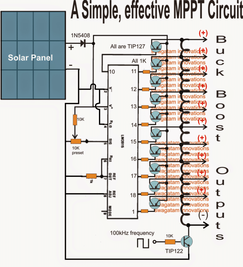
Using LM3915 as the Main Processor IC
The main processor in the above diagram is the IC LM3915 which switches its output pinout sequentially from the top to the bottom in response to the diminishing sun light
These outputs can be seen configured with switching power transistors which are in turn connected with the various taps of a ferrite single long inductor coil.
The lower most end of the inductor can be seen attached with a NPN power transistor which is switched at around 100kHz frequency from an externally configured oscillator circuit.
The power transistors connected with the outputs of the IC switch in response to the sequencing IC outputs, connecting the appropriate taps of the inductor with the panel voltage and the 100kHz frequency.
This inductor turns are appropriately calculated such that its various taps become compatible with the panel voltage as these are switched by the IC output driver stages.
Thus the proceedings make sure that while the sun intensity and the voltage drops, it's appropriately linked with the relevant tap of the inductor maintaining almost a constant voltage across all the given taps, as per their calculated ratings.
So I have explained the functioning with the help of the following scenario:
Suppose the coil is selected to be compatible with a 30V solar panel, therefore at peak sunshine let's assume that the upper most power transistor is switched ON by the IC which subjects the entire coil to oscillate, this allows the entire 30V to be available across the extreme ends of the coil.
Now suppose the sunlight drops by 3V and reduces its output to 27V, this is quickly sensed by the IC such that the first transistor from the top now switches OFF and the second transistor in the sequence switches ON.
The above action selects the second tap (27V tap) of the inductor from top executing a matching inductor tap to voltage response making sure that the coil oscillates optimally with the reduced voltage...similarly, now as the sunlight voltage drops further the respective transistors "shake hands" with the relevant inductor taps ensuring a perfect matching and efficient switching of the inductor, corresponding to the available solar voltages.
Due to the above matched response between the solar panel and the switching buck/boost inductor...the tap voltages over the relevant points can be assumed to maintain a constant voltage through out the day regardless of the sunlight situation....
For example suppose if the inductor is designed to produce 30V at the topmost tap followed by 27V, 24V, 21V, 18V, 15V, 12V, 9V, 6V, 3V, 0V across the subsequent taps, then all these voltages could be assumed to be constant over these taps regardless of the sunlight levels.
Also please remember that these voltage can be altered as per user specs for achieving higher or lower voltages than the panel voltage.
The above circuit can also be configured in the flyback topoogy as shown below:
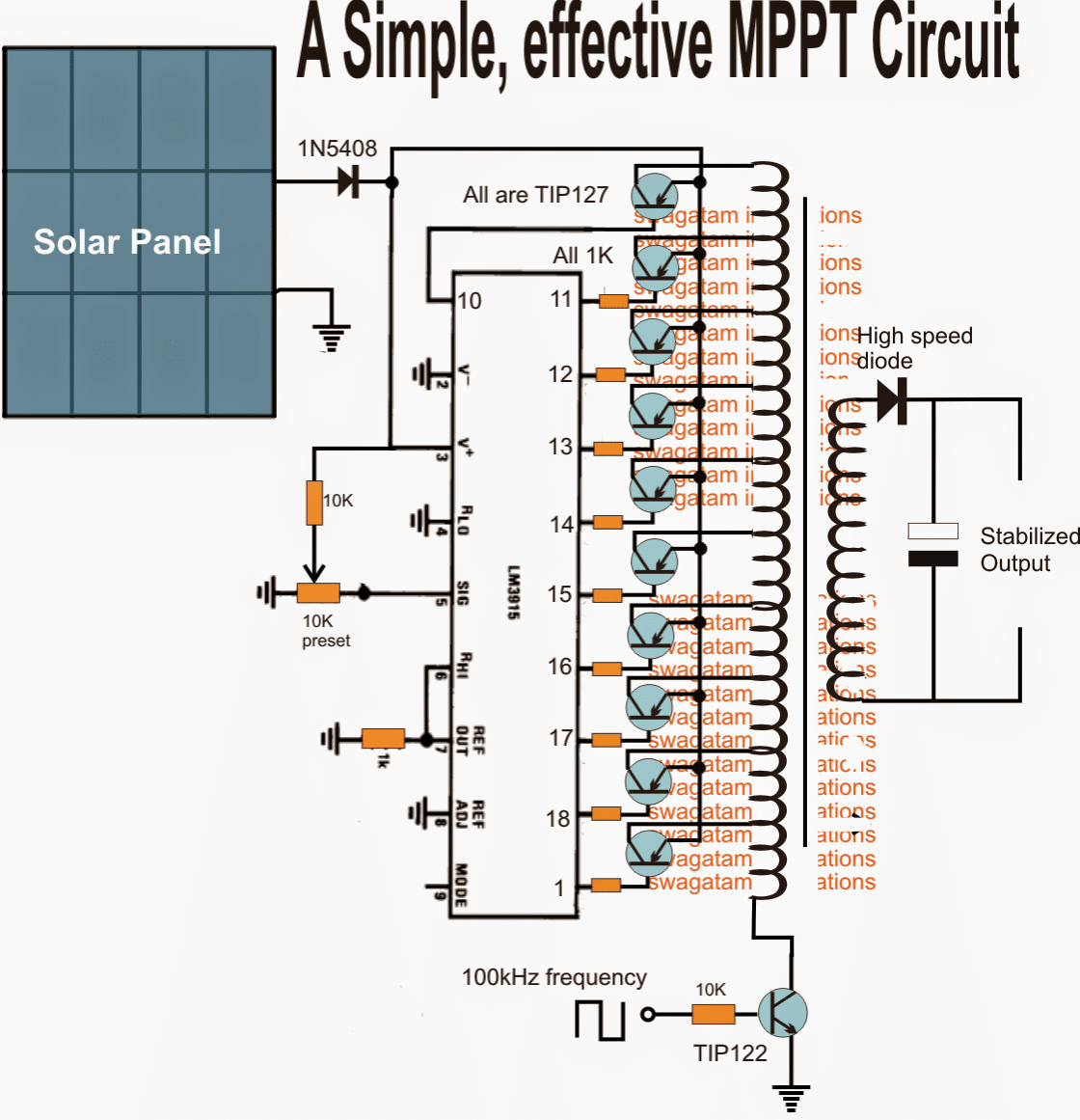
In both the above configurations, the output is supposed to remain constant and stable in terms of voltage and wattage regardless of the solar output.
Using I/V Tracking Method
The following circuit concept ensures that the MPPT level of the panel is never disturbed drastically by the load.
The circuit tracks the MPPT "knee" level of the panel and makes sure that the load is not allowed to consume anything more which might cause a dropping in this knee level of the panel.
I have explained how this can can done using a simple single opamp I/V tracking circuit.
Please note that the designs which are without a buck converter will never be able to optimize the excess voltage into equivalent current for the load, and might fail in this regard, which is considered as the crucial feature of any MPPT design.
A very simple yet effective MPPT type device can be made by employing a LM338 IC and an opamps.
In this concept which is designed by me, the op amp is configured in such a way that it keeps recording the instantaneous MPP data of the panel and compares it with the instantaneous load consumption. If it finds the load consumption exceeding this stored data, it cuts off the load...
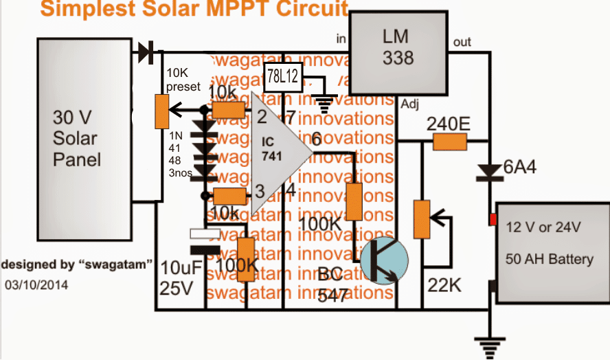
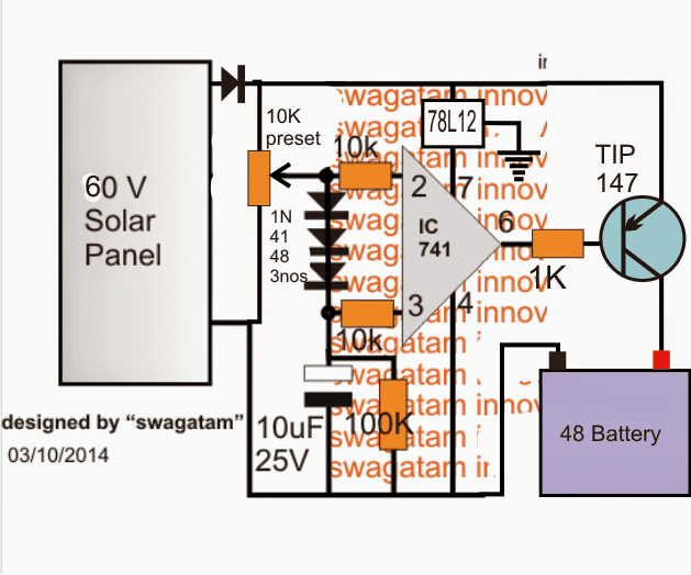
The IC 741 stage is the solar tracker section and forms the heart of the entire design.
The solar panel voltage is fed to the inverting pin2 of the IC, while the the same is applied to the non-inverting pin3 with a drop of around 2 V using three 1N4148 diodes in series.
The above situation consistently keeps the pin3 of the IC a shade lower than pin2 ensuring a zero voltage across the output pin6 of the IC.
However in an event of an inefficient overload, such as a mismatched battery or a high current battery, the solar panel voltage tends to get pulled down by the load. When this happens pin2 voltage also begins dropping, however due to the presence of the 10uF capacitor at pin3, its potential stays solid and does not respond to the above drop.
The situation instantly forces pin3 to go high than pin2, which in turn toggles pin6 high, switching ON the BJT BC547.
BC547 now immediately disables LM338 cutting off the voltage to the battery, the cycle keeps switching at a rapid pace depending upon the IC's rated speed.
The above operations make sure that the solar panel voltage never drops or gets pulled down by the load, maintaining an MPPT like condition throughout.
Since a linear IC LM338 is used, the circuit could be yet again a bit inefficient....the remedy is to replace the LM338 stage with a buck converter...that would make the design extremely versatile and comparable to a true MPPT.
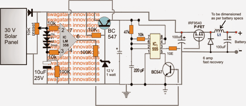
Below shown is an MPPT circuit using a buck converter topology, now the design makes a lot of sense and looks much closer to a true MPPT
48V MPPT Circuit
The above simple MPPT circuits can be also modified for implementing high voltage battery charging, such as the following 48V battery MPPT charger circuit.
The ideas are all exclusively developed by me.


Questions & Answers
Good morning, it’s been a long time I spoke to you last, sir. i hope everything is doing great. I built a solar charge controller(steping doewn higher DC voltage to 5v DC) using lm2596 and some other components to see input and output voltage, my solar panel is three panel(9v, 9v, 6v) panell connected in series, under open circuit the voltage is 30v. now after the project has been completed I noticed the heatsink i attached to lm2596 is very hot, I checked online and I was due to large voltage ratio(30v : 5v), so I want to implement crude mppt and maybe even uvlo, I found a circuit on YouTube so I want you to check it sir, change all components to work for my solar spec.
this is the image:
https://drive.google.com/file/d/1A5M-chQPYavZD20b4SkqPXvOXlvHCvFy/view?usp=drivesdk
Hi Jerry, the LM2596 is a buck converter, not a linear regulator, so it should not heat up too much even if the voltage differential is large. However it may heat up if the load current draw is large.
What is your load current?
By the way you can try the following version if your current requirement is bigger:
https://www.homemade-circuits.com/0-to-50-v-adjustable-switching-power-supply-circuit-using-ic-lm2576/
The linear regulator at the input side is simply not required, because then your linear regulator will start dissipating heat, and the whole purpose of using the buck converter would be defeated…
pls pardon me, I meant a buck converter that use of lm2596, also I intend to implement a crude mppt by adding this circuit I found on YouTube, pls sir help check it out will it work? my load current is just under 2A.
Yes, it should work to control and maintain the MPP level of the solar panel…
Dear Swagatam
I hope you are doing fine. I have seen several MPPT circuits from your site however in local market I have seen another one which is going strong as far as its specs are concerned.
The setup is where 7 Solar plates are connected in Series and returning 48 Volt + 7 = 336 Volts total. This voltage is given as Input to a so called MPPT local device (a locally made Desi version) and its output is 230V 7 to 10 kva. The AC and fridges are connected at its output.
My understanding is since higher DC voltage is connected and used so copper in transformer (if any) should be minimal and so the ratio of primary and secondary and power conversion losses are lowest as well but I am not sure what circuit is actually used. Can you suggest as what might be used or can create one.
Regards
Thank you Abdus, for your interesting question.
The copper that you are suggesting is the copper winding I guess.
The copper winding should be as per the calculations and the operating frequency, which must be precisely implemented.
To minimize losses the copper wire can be in the form of multiple thin wire strands instead of a single thick wire, which minimizes skin effect and increase efficiency. The core of the transformer is mostly ferrite so the core losses are already minimal.
Commercial MPPT circuits can be quite complex and sophisticated, which might be beyond the reach of my expertise, so designing them could be difficult for me.
Dear Swagatam
Thanks for your quick response.
No I am not expecting some very sophisticated device but I love your home grown solutions so just a little understanding for something quick trick may work for me. You can direct me to some already made schematics or a group of schematics so I can start experimenting with it. Moreover in starting version it may not be a very powerful device but rather a proof of concept version for 1KVA or similar and I can later experiment with it for more power. Its for my personal endeavor so need to be a commercial project.
Local commercially sold unit cannot be said to be professional one either for instance there are No charging batteries etc. Local community is using it till 4PM with said load and turns off AC after that and after 5PM turns off fridges as well but fans etc. are working till 6PM and after that whole system is turned off. This turnoff of loads as discussed above is done manually.
Still if it is not viable as a personal project then its fine. I shall still search for it and if found out then I shall also share it with you.
Thanks for your co-operation and responses.
Regards
Thank you Abdus,

If you want to experiment with an MPPT concept then I would recommend you the second design from the above article.
It is the most viable looking MPPT design because it exploits the basic voltage/current conversion principle of a transformer, which makes sense.
You can initially experiment using a small iron core transformer for a small 100 watt load, just to check if the concept really works or not.
Although the results might not be too accurate, still it should be good enough.
For an iron core transformer the switching frequency to the TIP122 must not exceed 60 Hz.
I have a 560ah 24V LiFePo4 battery. I have a BMS that monitors each cell and will disconnect the panel from the battery if any one cell exceeds 3.5V. There is no charge controller. I want to try your circuit to see if it will do a better job of matching to the panel’s optimum power output. The battery is typically at 27V and the panel’s optimum is 33V, so I am probably not getting as much power as possible.
Note, I don’t need the MPPT to taper the current to achieve max charge, because the Sun does the tapering for free each day. I just need the MPPT to deliver as much power as the panel will provide, and of course shut off when the BMS opens a circuit.
Am I correct to conclude that the “Simplest Solar MPPT Circuit” will do the job?
Is the version with the buck converter only more efficient? In that circuit what should L1 be?
Thanks for this excellent article!
Thank you for visiting this site! The opamp based simple MPPT circuit is designed to cut off the load whenever it tries to exceed the MPP specifications of the panel, preventing the solar panel from dropping below the MPP level. The cut off and restoration process is switched continuously ensuring that the panel output always remains within the MPP zone. You can try it and check the response.
The buck converter is presented only as a concept, the actual part values are not known. You can try integrating some other buck converter circuit with known part values.
Oh hang on, this is not going to do the T part of MPPT. It won’t track, right? I will only maintain the panel at a set voltage. MPP specifications includes temperature, which means that this circuit will match the MPP only if the temperature matched, right?
Have you designed a circuit that will hunt for the max power?
Yes that’s correct, the op amp circuit will only make sure that the load does not destroy the knee voltage of the panel at any instant.
For hunting max power the first two circuits can be used. But even these circuits simulate MPPT, they are not real MPPT. The first two circuits will continuously track the panel voltage and try to match it with the transformer winding voltage levels to ensure that the output load is able to extract the maximum power from the panel.
We have a crank/pedal powered device that outputs 300 watts (50 volts). We intend to recharge two 12 volt 65 AH batteries by channeling the output through an MPPT. As the generator is pedal powered, power generation will not be constant but will vary with the pedalling, which is why we thought of the MPPT.
We think that the output from the MPPT should be sent to each battery separately for charging.
Can you help us with a design for a circuit for this purpose, or is a readily available MPPT capable of handling the outpower appropriate for the job.
I don’t think MPPT would be required in your case. If your pedaling speed reduces the MPPT will not be able to increase the current from the system.
Instead, you can try a buck converter circuit for converting your 50V to 14 V, that will be very efficient.
My thinking was:
If the generator output is 300 watts, and charging a 12v 65AH battery requires only 78 watts (12 x 6.5, ie 10% though I am told we can charge up to 20% of 65, ie 13), the excess power would be unutilised. If I connect two batteries in parallel to the MPPT I can charge two similar batteries at the same time.
A buck converter will reduce the voltage but will it enable charging of two batteries? We think we will be able to keep the voltage from going below 50V
An MPPT also uses a buck converter which makes sure that the excess power is not wasted. 10% rate is the recommended rate for a lead acid battery which ensures an increased life for the battery. If you use a buck converter then the 50 – 12 = 38V would be converted into excess current so that you can even charge 3 batteries in parallel at 6.5 amp rate.
I can’t figure out how an MPPT could be used with a generator.
please how can I make a good buck converter for 60v 10amps to 24v battery system
You can try the following design:
https://www.homemade-circuits.com/lm317-variable-switch-mode-power-supply/
Replace the PNP transistor with TIP36.
Make sure the IC is LM317-HV, the HV version can handle upto 60V input.
I didn’t know that a buck converter would convert excess voltage into amps, I thought only MPPTs did that.
So I can connect 3 batteries of equal voltage to the output of the buck converter to charge them?
Yes, that’s the main purpose of a buck converter. If your buck converter is highly efficient then 3 batteries may be possible otherwise only 2.5 batteries.
Thanks for the reply. I have not yet connected the MPPT. I spoke to a manufacturer. The idea is to convert the generator output to DC using diodes, then from the diodes to the input of the MPPT.
I have no electrical or electronics background. Just an idea I am pursuing.
I checked online and found that yes MPPT works with generators, but buck converter is a much easier and cheaper option. However you can try a readymade MPPT circuit with your generator it will work.
Hi, thanks for the inspiration.
Regarding the circuit for the following,
How to achieve the final setting for the 10k preset?
Do you have guidelines for sizing the choke L1?
After revising the details I realize that the 10K preset should not be there. The inverting input of the op amp should be directly connected with the solar panel.
However, for this to work, the op amp rating must be higher than the solar voltage. For example any op amp with 32V rating could be selected and a solar panel lower than 32V could be used with the op amp circuit.
How hard is it to dsign a 12 kW DC-DC converter to convert power from an Electric Vehicle battery (325-400VDC) to 138.6VDC to run my APC Symmetra UPS on DC?
Fantastic article! Thank you for contributing!
How can I contact you to discuss a custom MPPT? Cannot post the details of the project publicly now.
I prefer discussing through comments only, sorry about it.
Hi,I will build this circuit any modifications?
Thank you for your projects..
Hi, I’m trying to build an all in one inverter+charger with 48V solar input with MPPT and battery and grid bidirectional converters so I can charge the batteries and once they’re full redirect power to grid. be able to get power from the grid and the batteries
Something like a Eg4 3000 ehv-48
I would like to know if you have any circuits for this
Hi, that appears to be quite complex and big, I do not have this design with me at this moment.
I have 36volt solar (4.4amps) and I want to charge a 12v battery which will be connected to an inverter (150 watt), which of the circuit can I use to achieve an mppt output from the panel.
You can try the second design, or you can also try the following design:
https://www.homemade-circuits.com/0-to-50-v-adjustable-switching-power-supply-circuit-using-ic-lm2576/
Hi:
I am trying to build a DC MPPT controller of a sort. Probably better to call it a MPPT limiter. I want to power an electric oil radiator type heater (no fans, manual thermostat) directly from a small solar array (3 x 500w panels in series). Panels are rated at 545W, OCV 49.6V, MPPV 41.8V, SCI 13.92A, MPPI 13.04A. This would give max power output at about 125 vdc and about 13A. I need to keep the panels as close as possible to MPPT at full output, of course if the solar output is lower it would just run at the available voltage and current. I don’t want to use a voltage boost converter, I just want to limit the maximum output of the solar array to the MPPT. Load resistance would be around 10 ohms for a 1500w heater. Maximum efficiency without inverters or boost converters is the goal.
The 48v circuit is interesting, but I don’t see how it maintains a constant charge voltage for the battery or even senses battery voltage at all. Could I simply substitute an SSR for the TIP147 to handle the appropriate load current and just have a bang bang controller?
Hi,
I agree with you…the last circuit which is a 48V battery MPPT type charger does not have a voltage regulator. The circuit only detects an over current and cuts off the supply. It makes sure the panel voltage is never allowed to drop below its maximum rated output except a margin of around 2%. I will try to upgrade the last circuit with a voltage regulator soon.
However for a crude load such as a heater coil the voltage regulation may not be crucial, and only the MPPT regulator as suggested in the 48V circuit should be enough.
Sir:
The circuit as it stands does not monitor current, only panel voltage, so it can’t directly “detect an over current”, other than indirectly by detecting the panel voltage dropping.
I assume you set the pot so the circuit trips at or just below the MPP voltage of the panel(s). You didn’t address my question about the SSR. The TIP147 does not have the current or voltage capacity to handle a 120VDC solar array at 13A, but a 25A or 40A SSR with an DC rating of 220v would easily handle this load. What kind of frequency does this oscillate at when switching? It looks like it would sort of output a variable frequency PWM while it is regulating, the SSR would need to be able to operate at this frequency. I assume the 100K/10uF time constant would affect this?
Would this rapid switching of load current on the solar panels generate a lot of EMI/RFI? Or cause some detrimental effect on the system?
Silicon Alchemist, the 48V circuit will cut off the supply to the load when the panel voltage starts dropping, which can only happen when the load draws high amount of current. So indirectly the circuit will monitor an excess current consumption by the load. The pot actually can be used to determine the output voltage but ideally it should be used to fine-tune the MPP cut off.
You can replace the transistor with an SSR which can be used to handle higher voltages easily.
The output oscillation will be a kind of variable frequency PWM and will depend on the load current consumption and the panel voltage level. There could be some EMI generated just as we have in zener diodes.
If the load is a sensitive CMOS device or an audio amplifier then this frequency might have some effect on it.
Hi Swagatam,
Can we use the last 48v circuit without a buck on a resistive load like a water heater without a battery? I do PV direct water heating at the moment using a 48vdc element and was wondering if this design can improve the efficiency and maintain my input PV voltage.
Regards
Musa
Hi Musa,
yes, you can use the last circuit for resistive loads effectively. The circuit will cut off whenever the load tries to consume excess power beyond the capacity of the solar panel and thus will maintain optimal power output from the panel
Hi Swagatam,
Tried it with my setup and realized my current is a bit more than what the circuit can handle. Some smoke came out and there was a little bit of heat. I need to change some components to accommodate my 43V and 20A open from my panels.
Please advise on which components to modify to accommodate my input (43V and 20A).
Regards
Musa
Hi Musa,
The 7812 IC can handle a maximum of 35V, it will burn at anything above 35V. I am not sure if your 741 IC is also burned or not?
You can replace the 7812 with the following transistorized regulator circuit and check if this helps. The zener diode value can be a 12V 1 watt zener. Also the transistor TIP147 can handle a max current of 2 or 3amps without heating up.
GOOD job bross , I can see that knowledge is there for u
If I may ask you can you be supplying me some of these designs in which I we just be housing them here.
I,m from Nigeria here ?
No problem Akintunde, let me know what exactly you want, I will try to help…
I have the following setup: 204Vmp(max) x 25A PV + 100.8V(max) x 30A 24S Li-Po + 5kW(98V) BLDC.
I cannot find an MPPT for the above. Would it be possible to make my own? Any schematics? Thanks.
(I’m a Mech.Engr.& programmer, not Electrical Engr.)
Sorry, presently I do not have an MPPT circuit for the mentioned BLDC motor
If i connect 160v dc to MPPT it will convert 12v with out lose ampere
yes if the inductor transformer is selected correctly
Sir I mean the fourth circuit that is using 555timer IC and single opamp IC, this circuit is not working and you didn’t make any explanation for this circuit.
Emmanuel, the IC 555 circuit is a complex circuit and you must build it with step step up testing and by understanding the stages perfectly. If you do it without understanding it then it will never work.
First confirm the op amp stage using meters and the explanation provided in the above article.
Once the op amp stage is confirmed then you can build the buck converter stage.
For understanding the 555 buck converter you will have to first learn how a buck converter works.
If I possible I will add the explanation soon for the 555 buck converter.
You have not explained anything on the working principles under the MPPT circuit diagram please kindly do that for me sir.
The circuit works using the standard step down transformer principle. The circuit adjusts the transformer tapping with the solar panel voltage and matches them appropriately, so that the right winding gets the right voltage from the solar panel. When this happens the output voltage remains constant, and also output current remains optimally adjusted regardless of the solar panel voltage
Thank you sir.
What will happen if a bulk converter is connected directly to Solar panel and then to load without mppt.?
Hi Onyi, Buck converter will work very nicely almost like an MPPT, but you must have an over charge auto cut off for the battery, to prevent over charging
do you have diagram for 80 amps MPPT? Thanks in advance.
sorry I don’t have it at this moment….
Hi Swagatam,
Really excited to find this!!
Just one clarifcation, can we charge Lithium ion or LiFePO4 battery. If so please provide specification.
Thank you Adithya, yes definitely you can charge Li-ion or LiFePO4 battery with the above MPPT. For charging these batteries you can use the circuit explained in the following article, just make sure to use a current that’s 50% less than the mAh value of the battery
USB 3.7V Li-Ion Battery Charger Circuit
Hello Engr. Swag.
Many thanks for your selfless and invaluable efforts in throwing out for free and demystifying top secret in electronics which other Engineers would have converted into money.
Could you give me a simple 12v mppt based charge controller circuit, as updated.
Thanks.
Thank you Engr Bayo, a simple MPPT circuit created by me is shown in the above article (second diagram) which will give you 100 % working results using ordinary components.
Hi Swagatam,
Please can you shed more light on the type of ferrite single long inductor coil used in the diagram? And what is the value of the capacitor in the output?
What is the current output rating of the circuit ( Number 2 diagram)?
You will have to find it through some trial and error, you can use 1.25 times the input voltage initially and tweak the turns with the help of a voltmeter attached to the output taps.
This is excellent reading. Thank you
MERRY CHRISTMAS, AND A LOT OF STRENGTH IN 2021. IN THIS LAST CIRCUIT, I INTEND TO USE TWO PANELS THAT ADD, ARE 70 VOLTS AND 9 AMPERE, FOR FOUR BATTERIES 12 VOLTS IN SERIES. BEING SO I HAVE TO CONNECT A THICK WIRE, THAT LEADS 9 AMPERE IN TIP 147, IS IT REALLY?
Merry Christmas to you and also wishing a happier and a safer 2021 to you.
You can definitely try the last circuit for your application.
However, TIP147 might not be sufficient to handle 9 amps….you can instead replace the TIP with a IRF9540 MOSFET, it will do the job for you perfectly.
THANKS. BUT DOES THE 1K RESISTOR CONTINUE THE SAME? THANKS.
For a MOSFET the 1k can be any value, it is immaterial. For transistor it will need to be calculated using the for a as explained in the following article
Transistor Relay Driver Circuit with Formula and Calculations
HELLO HOW ARE YOU? THIS 48V CIRCUIT AND 60 V PANEL, CAN I USE 4 12V BATTERIES IN SERIES, BUT WITH A 75V AND 9 AP PANEL, APPROXIMATELY? WHAT SHOULD I MODIFY?
Hi, yes definitely, you can use the last circuit from the above article to charge your 48V battery from a 75V panel
Pls is there any other MPPT circuit for 60amps/24v?
Sorry, presently I do not have a 60 amp design
Pls Mr swag,I need complete through 60amps 24v MPPT controller.Which of your article can be used and what modifications is needed?
You can try the concept explained in the above article (1st design) but for 60 amps the transformer will be huge, unless it is a ferrite based design
Swagatam, Thank you for you ideas and suggestions
Glad to help!
I am looking to make a MPPT to power the electrodes in a salt water swimming pool chlorinator. The pump is 72volt DC and runs direct off the panels via its own MPPT. – no battery. Using a 12 volt panel(s) would like to feed straight to the electrodes in the chlorinator unit. The electrodes need 8-12volts at a current of 15-20 amps. Would one of your MPPT circuits be able to achieve this without the battery connection? The MPPT can be switched on by a flow switch situated in the pump supply or discharge line. (the pump is in flood so water will flow the second the pump starts)
The inductor based MPPT explained might surely work, however the high frequency transformers are not calculated, and using an iron core trasformer might make the design huge and bulky.
Instead I would recommend using professional and tested buck converter designs which should work as efficiently as an MPPT if the load is not exceeded above a specified level. Here are a few examples:
LM317 Variable Switch Mode Power Supply (SMPS) You may have to upgrade the transistor Q1 value to support 10 to 15 amps
PWM Solar Battery Charger Circuit The resistors R8/R9 should be adjusted for getting a 12 V output.
https://www.ti.com/lit/ds/symlink/lm5145.pdf?ts=1592229037795&ref_url=https%253A%252F%252Fwww.ti.com%252Fproduct%252FLM5145
Hello sir, please help me with the formula to calculate the number of turns and amperage of the above 2 mppt transformers. Thanks Abbey.
Abbey, you can use the second concept from top, it uses an ordinary iron core transformer having multiple primary taps, 3V,4.5V, 6V…..24V and so on. The secondary output could be 220V, for low voltage output, you can extract them across the primary taps itself.
Good morning Mr Swagatam, I really appreciate your character of been prompt to reply every questions sent to you, thanks a lot and have a nice day. Abbey.
You are welcome Abbey!
Each of the outputs of the LM3915 acts simply as a switch that flips when the input voltage from the panel crosses the threshold defined for that op-amp by the IC’s internal resistors. All the outputs from the IC generate the same voltage, so all the BJT’s gate at the same voltage, and the resistors between the BJT’s and the IC are the same as well. Could you accomplish the same effect by using a single op-amp, configured for a precise, low gain, and pairing each BJT with two resistors of precise values, as a voltage divider, chosen to admit the voltage necessary to gate that BJT only when the amp is receiving current from the panel at a particular voltage?
In the above concept, the main MPPT execution is done by the transformer through the matching of its various taps with the solar voltage.
The PNP only act as switches that’s correct, and the IC matches the solar voltage appropriately with the most relevant tap of the transformer through the PNP switches, as per a predetermined setting.
With a single opamp we cannot switch the different taps of the transformer and therefore cannot accomplish the required MPPT effect.
sir we have 240 battery bank we need 240 volt mppt Gharge controler circuit idyas in ower solar panel open volt is 360
Hello annamalai, you can try implementing the first two simple concepts explained above, the transformer winding can be modified as per your charging specifications
As I understand it, the LM3915 contains a voltage reference, ten op-amps, and various resistors used as voltage dividers, such that it switches among outputs with varying input voltage. As shown in the first illustration, it gates the TIP127’s to direct current from the panel through the best-suited length of inductor coil according to incident voltage. But the differences in magnitude between the outputs of the LM3915 are inherent to the design – they can’t be changed by the user, so the connections to the inductor have to be placed carefully to match them. Could the efficiency of the design be improved by placing the inductor taps at regular intervals – or using discrete inductors in series – and replacing the LM3915 with discrete components, chosen carefully to match the inductance values of each connection to the inductor? If so, could the efficiency be improved further by adding a greater number of outputs, with smaller differences between them?
Yes the output will sequence at uniform steps in response to the corresponding increase or decrease in the solar voltage. WE can note down at what input voltages the output shifts, and accordingly dimension the coil data, so that the two operations become compatible with each other. Alternatively we could go for discrete opamp based sensor, as used in this concept:
https://www.homemade-circuits.com/5-kva-to-10-kva-automatic-voltage-stabilizer-circuit-220-volts-120-volts/
What’s the advantage of discrete op-amps? Would it become more efficient if you used more steps?
discrete opamp will allow us to adjust the changeover thresholds as per our desired specs. LM3915 will do as per its own fixed specs, and this will be uniform across the whose range…I think LM3915 is a better option
good day Eng Swag,
please do you have any solar mppt circuit diagram that can output upto 300vdc with input between 200-300vdc?
thanks
Matt, I only have a buck converter based MPPT, I do not have a buck-boost based design yet
Hello sir,please may explain a difficulty and ask a question based on it.based on the first and second diagrams.that is the buck/boost configuration.I checked online for awg wire current and frequency rating and found that the thickest wire to operate at 100khz with 100% skin depth is awg26.but this wire is able to carry only 0.361amp .so to get 5amps we will need to wound 15 wires together,meaning one will deal with 30 wires at each tap. The question is”can the circuit be operated at a lower frequency”? Say 8-40khz. Which will allow the use of awg15-22. Reducing wire to 1-5
Hi Shedrach, It seems you might have missed something, your analysis might be wrong. frequency is related with number of turns, not with wire AWG or thickness. However number of turns is related to current, more turn numbers allow less current and vice versa.
at higher frequencies the turns number decreases proportionately and vice versa, therefore at higher frequencies number of turns become less allowing smaller inductors to be used.
you can use any transformer by suitably matching the frequency specs, but lower frequency will mean incorporating bigger transformers and bulkier installation.
for improving skin depth you can use stranded type copper wire having many bifilar wires compacted together.
you can find the wire thickness required for 5 amp at 100kHz, then use stranded wire for that thickness to make things easier and efficient, for example if the required thickness is 14 AWG, we can use stranded 14 AWG wire and effectively minimize the volume of the transformer
Sir I want to convert 60v DC to 12v DC…please Help.. 60v is solar panel.
Sir I want to convert 60v DC to 12v DC…please Help.. 60v is solar panel.
Prasad, you can build the last circuit from the following article:
https://www.homemade-circuits.com/5v-pwm-solar-battery-charger-circuit/
you can try the following circuit
https://www.homemade-circuits.com/lm317-variable-switch-mode-power-supply/
Please Sir, can someone use laminated transformer (I E) type for the mppt discussed above? Thanks Abbey.
Abbey, yes iron core transformer can be used for the above discussed concept.
plz ..your link iz not working …..not found
Sir I want to convert 60v DC to 12v DC…please Help.. 60v is solar panel.
which link is not working??
Sir I want to convert 60v DC to 12v DC…please Help.. 60v is solar panel.
Dear sir,
Please send me 48 volt only low dc cut off circuit
Dear sir,
Input dc voltage 48volt so, please advice provided circuit is working correctly and how to adjust voltage
Hi Manj,
you can use the same circuit for 48V also, just make sure the relay is 48V rated, and use BC546, BC556 instead of BC547, BC557
apply the specified low voltage level from the battery side, and adjust the preset such that the relay just clicks ON….that’s all.
now if you increase the voltage, the relay will switch OFF, but the margin could be around 2 to 3V
Dear sir
Please provide the 48v to 12v DC to DC converter circuit if using lm 317 or 7812
Dear sir,
Please provide AC to dc 12 volt without transformer circuit
you can try this
https://www.homemade-circuits.com/2015/01/calculating-capacitor-current-in.html
Dear sir,
Thanks for reply but my requirement is only 5 to 10 second timer circuit so please provide
you can reduce R2, C1 value to get the desired timing delay.
Dear sir,
Please provide the 5 second delay timer circuit using ic 555 and operated 12 volt really if on the switch.than start circuit
(Input voltage 12v)
Manoj,
you can try the following design
https://www.homemade-circuits.com/2014/06/input-trigger-synchronized-monostable.html
put the push button at the points shown as “left pin”
Dear Manoj, you can try the following design
https://www.homemade-circuits.com/2016/08/0-60v-lm317-variable-power-supply.html
Dear Manoj,
you can try the last design from this post
https://www.homemade-circuits.com/2013/05/low-battery-indicator-circuit-using-two.html
Hello sir!
i am a student of B.tech electrical. i am working on my final year project. Sir i want to make an MPPT Charge controller of rating 200 watt panel. kindly sir guide me how can i make this without using the microcontroller. some suitable circuit diagram. plzzz sir.i have seen many articles of mppt of yours. butt i am confused. suggest me the best suitable diagram of my rating. your help will be highly appreciated.
Thank you so much Sir!
Hello Imran,
You can try the following concept, if you build it correctly step wise it will solve your purpose
https://www.homemade-circuits.com/2015/11/simple-solar-mppt-circuit-part-2.html
Hi.Sir Swagatam Majumdar.Sir we are working on Perturb and observe method.Can u provide me with a working dc-dc converter circuit diagram.Range having input 8-20 volts and output range 9-22.thanks
Hi Mohammed, I have not yet researched this concept, if possible I'll do it and try to design a suitable circuit with this concept.
This is NOT an MPPT controller!!!!!!!!!!!!
I have 200 watts solar panel and i want to build mppt solar charge controller, please send me circuit diagram and component list.
you can refer to the following concept:
https://www.homemade-circuits.com/2014/11/self-optimizing-solar-pwm-charger.html
and also read this:
https://www.homemade-circuits.com/2015/04/mppt-solar-tracker-difference.html
Another quick question please. In the schematic for the 48v version, isn't the 78L12 receiving excessive voltage from the 60V solar panel?
yes you are right, a 78XX will not work here, you can replace it with the common collector stage as shown in the second last circuit above…using the BC547 and its base zener diode/resistor design
Dear Swagatam,
Thank you for providing such brilliant guidance. I am designing a 48v charge controller to hook up with the 200 AH battery bank. The panels array is rated approx. 2000 watts. The batteries are attached to a 3kw ups. This arrangement mainly runs a air conditioner (1200 watts) in summers. Therefore the amps flowing through the system are a lot (2kw@48v). I had a charge controller of 50 amps which is now broken and it costs around 150 usd. I don't plan on buying a new one. Instead I'm going to use your circuits with some modifications like mechanical on/off switches and additional transistor stages to pass all that power. Or perhaps replace the transistors with heavy duty triacs or even high amp car relays in parallel. My question is if I will be able to drive many transistors from the pin 6 of the 741 ic. Is there a circuit simulation software I can use first? Like a spice variant which has IC packages like 741 and 555 that I can employ to test the whole thing? Sorry for so many questions but sensing that you are a noble person who likes to help others I thank you in anticipation for your guidance. Stay blessed.
Mooney, you can try the following circuit:
https://www.homemade-circuits.com/2015/05/5v-pwm-solar-battery-charger-circuit.html
Still waiting for the update. Bro Majumdar its not so necessary to make it mppt. It just needs to be efficient. Its meant for poor people any way. A full bridge buck converter that can handle the amps and its limits governed by a few ICs may as well do the trick.
Sure Bro! I am always ready to help! However the above circuits were built on an mistaken assumption…so it wouldn't be a good idea to try these circuits won't simulate an MPpT, In my previous comment I suggested you an alternative circuit I would recommend you to try that instead of the above.
Or you can also try the earlier link that I had referred using IC 555 IC.
I would be updating the article soon with a correct version so that the circuits works more like an MPpT.
Brother forgive me but kindly do me this one favor only, modify the 48 volt circuit on this very page only to handle 2 kilo watts of power. The more I read about drive requirements for transistors and mosfets the more I feel ignorant about them. You're the guru so please guru ustad take the time to make this small modification. I will acquire the PNP transistors and everything else. This one here, aptly named Poor man's mppt is the best of them all when it comes to simplicity and efficiency.
Sorry bro, you cannot use relays here, because the switching is supposed to be very rapid, either a mosfet or a transistor will only work for the above circuits.
for the time being you could rather try building the last design from the following article, I would recommend this one as its much easier and makes more sense:
https://www.homemade-circuits.com/2013/08/simple-zero-drop-solar-charger-circuit.html
Okay thank you Swagatam, I'll be looking forward to it. In the mean time, I think I am going to build the circuit on this page and instead of a transistor I'm going to use a bunch of car relays driven by the 741. I hope the IC will not be switching them too much because I do not want the inductive kickback spikes from fast switching relays to damage the UPS. Am going to start building this ASAP. I intended to send you report and photos of any build designed by you so I will send you photos of it, hopefully.
Thanks bro, for the nice explanation, I'll try to design and publish the required circuit, specific to your application. It may take some time though, since it would be quite an elaborate article and might take a lot of thinking…..
cheers!.
It is, and I hate to whine to you but it uses a P channel mosfet. Being rare (for some reason), P channel power mosfets are expensive over here, like a dollar for one. Then, I am located far away living on a farm in remote Punjab. I have plenty of n channel mosfets and transistors though and the usual items like 555's, 324's, 741s, and a whole lot of scrap including transformers from local made UPS units.
The other concern I have is that internet searches bring forth the advanced concepts like H bridge and full bridge mosfets driven by the latest ICs which I do not have. I could try and hunt for 3524 or other PWM and FET driving ICs. But the coolest idea of a 555 based PWM driving mosfets and "chopping" the power coming down from the solar panels and tailoring it to my need seems most feasible to me for now.
I have made simulations of all the circuits you have developed, all of them, however they don't simulate very well because the applet I'm using, developed by Paul Falstad, does not have a PV input. Otherwise the circuit you have shown here is quite good being simple. Secondly the PV array is 2 kilo watts of power. And I'm not sure how to add mosfets to share the power. To be honest, Mosfets are sophisticated things with a lot of "nakhra" to take care of in their design, as you know.
I could use a small army of D1047 NPN transistors instead if need be (I have plenty of these from scrap), driven by a 555 based PWM and a 741 or two as comparators, sensing and controlling the voltage limits as long as the circuit doesn't let them go linear to waste the power being conducted down. But I am a newbie so I'm not so confident in designing it. I also have a box full of IRFP150N n cannel mosfets.
Bro you agreed to help me. Perhaps you could take the time to design such a thing for me? Pretty please. My wife and children are visiting their parents and I want to get the solar power up and running by the time they return which is a week from now. And with all the frequent rains I don't have much outdoor farming work to do anyway. What do you say dear bro? 🙂
I know it bro, I thought you'd find it difficult to build the PWM version and therefore I referred a simpler option to you.
For the PWM version you can take a peek at this article, I think this is exactly what you may be looking for:
https://www.homemade-circuits.com/2014/11/self-optimizing-solar-pwm-charger.html
The problem with transistors and linear regulation is waste of a lot of power. I don't want that bro. What I need is mosfets switching by pwm signal and not wasting power. Op amps can control the switching. If you google "the back shed mppt circuit" you will find what I have explained. Bro I need your kind consideration upon that one, please. Its gorgeous and succinct.
Thanks bro, the pleasure is all mine. yes the circuit can be made automatic simply by adding the following design with its output:
https://www.homemade-circuits.com/2012/08/make-this-48v-automatic-battery-charger.html
the circuit actually can be enhanced in many different ways, as per the user preferences.
I feel extremely grateful to read that you are willing to take the time to help me. And that you have replied so quickly. Thanks bro.
The 100 amp variable voltage power supply design that you have linked is simply amazing and new to me. I can't appreciate the idea enough. However that one is missing automatic feature of a cut off to end charging when battery voltage drops below a certain lower limit like 50 volts or so. 50 is lower than the standing voltage of the batteries and it'll mean that the UPS is loaded and drawing power from them. The potentiometer in the circuit seems useful to have and I hope to use it in order to raise the voltage going to the batteries manually, only once a month, and give them an equalizing charge.
Thank you dear Mooney,
Actually I have never used a simulator in my life because I simply never needed these artificial means, I normally do the simulation in my mind much reliably…so I am afraid I have no idea about these things.
By the way if you say I could design the system for you, if you can specify the exact features that you would want the charger to include.
If you are interested to go for a simpler option here's one very simple circuit which will start charging your batteries as soon as you hook it up with the panels.
https://www.homemade-circuits.com/2015/03/100-amp-variable-voltage-power-supply.html
can I use this circut direct connect to load?
means the input of the circut connect to the output of the solar and the output of circut connect to 12v dc fan.
can this can work good?
yes it can be done……
if all the component connect same like the above circut but If dont use 10k preset with this circut what would be the result?
can work fine or not?
if your panel output is below 24V then the preset can be removed, otherwise the preset will be required.
sir plz that one thing I dont understand 240E
or this is resistor?
it's a resistor = 240 ohms
HI, instead of using solar panels, can i use external power source/supply with appropriate voltage to charge battery?
Hi, the above circuits are designed to work with solar panels only, for a mains powered power supply the above complex design may not be required, you can simply use any standard design from this page:
https://www.homemade-circuits.com/search/label/Battery%20Charger
I have 150w panel round about 30 to 35v can I use this circut
and how much time they full fill bettery(50ah).thanks
yes you can connect it.
it will be difficult to predict the battery charging time because it could depend on many external factors.
Sir,
I am build the ciruit, but the output voltage is around 35 v , what I do ?
Ajith, did you set the circuit as directed in the article.
connect an LED in series with the emitter of the transistor, and switch ON the 35V input
next, without connecting any battery first adjust the preset such that the voltage at pin2 is 12V,
without any load this LED should stay switched OFF.
Now short the output terminals, LEd should light up now.
confirm the above and let me know.
Sir,
U mean 48v mppt controller circuit ?
Which diode connected in series with panel ?
yes that's correct, use a 10amp diode with the panel.
Hai sir,
I have two 35v165w panel. Can u use this circuit for charging 12v 100AH Battey ?
Hi Ajith, you can try the last circuit which is the simplest one, make sure to add a 6V zener in series with the base of the transistor.
connect the panels in parallel.
sir in your other pic for this project there is no trimmer atach
jeffery please provide me with the link, I'll check it out
Sir what is the value of the capacitor C in the middle of the circuit? its connected in the emitter of the BC547.
slide, please click the diagram to enlarge it….you'll find it to be 220pF
sir can u design the above solar charge controller for 48V 15A current level for MPPT tracking
Mayuresh, you can try the last circuit updated in the above article.
….and how would anybody charge a 100AH or a 200AH batt using LT3652
your designed circuit is not a true MPPT circuit, as expressed by JD Bakker. You fault him, but your headline is for an MPPT controller, which the circuit is not. As we say in America, that's false advertising.
Rather than just criticize, I will point you to a solution. Review the simple MPPT controller based on the Linear Technology LT3652. Quite an easy circuit to construct, actually MUCH easier than yours. Maybe instead of getting defensive, you should look for a true solution. You could also provide instructions to help enhance output capacity (charge current).
sir gud day,
thank you for your informative and helpful blog.
my some question is:
1.in R1,2,3 0.7ohms, how many watts i apply if my battery is 12v 40AH and my solar panel is 50w, 12v-20v. pls.. give me exact value of the resistor 1,2,3.
2.IC324 is it also LM324 if i buy in elect. store.
3.all 4 presets 10k parts under ic324 is it automatically set already or i manually configuring the value to set the right output, if manually do, will you mind how to set this in correct value.
Hope you appreciated me. Thanks very much!
The above circuit procedures could be quite complicated for anyone who may new in the field, it's for the experts….I'll try to update the article soon with an identical design but using lesser number of components and hassle free setting procedures….so please keep in touch until then
Why that much high rating 10 amp diode is used?
So that bigger batteries upto 100ah can be charged, you can use smaller diodes suiting your requirements.
The ground points must be connected to battery -ve or solar panel – ve
battery negative
Does it mean both the transistor emitter points should be connected
yes.
i made the circuit,but my solar panel is giving 10 volts without mppt but when the mppt is connected only 6 volts is measured. I measured this 6v by taking away the battery and connected a multimeter in place of battery it showed 6 volts. how can maximum power can be obtained with reduced voltage.
i connected 3 w 9v solar pannel and 12v 1.3AH battery
and the red led is always glowing even when the battery is dischearging
how can you charge a 12V batt with a 9v input?????
you will need a 18v panel for a 12v batt and the above circuit.
also replace the 4k7 pot under LM38 with a 10k pot for getting a 15V adjustable range
Where the ground in the circuit conneted?
transistor emitter lines need to be connected together
How to set the 10k preset values explain briefly?
pls make the circuit first, then I'll explain it further.
when will the red and green led's glow?
green = charging
red = batt full.
1) R1 R2 and R3 = 0.7/ charging rate in kilo ohms or ohms?
2) Is 4K7 is preset resistor?
1) it's in Ohms.
2)4k7 can be a preset or a pot. It should be a 10k preset/pot actually
In the circuit one transistor base is connected to 100 ohms and after that an a connection with big dot is left freely what to connect there?
ignore the dot, remove it from the circuit, it's a drawing mistake.
hi!
thanks a lot in helping me in completing the dual axis solar tracker it's working perfectly
my next step is to connect the solar panel of dual axis solar tracker to this simple mppt circuit
is this idea good
Here in the circuit A3 and A4 are the other 1/2 of IC 324 then in circuit A3 is +v and ground connection are these connections pin 4 and 11 in IC 324?
I would recommend the simpler zero drop charger design which is shown below, it's basically a voltage regulator circuit that optimizes the solar parameters and avoids unnecessary loading of the panel.
https://www.homemade-circuits.com/2013/08/simple-zero-drop-solar-charger-circuit.html
You are welcome!
The IC 324 has four quad opamps in one package, the supply for the entire IC is at the pins 4 and 11.
hi i am planning to connect this mppt circuit io dual axis solar tracker.
1) if my solar pannel rating is 50w what must be the R1,R2,R3 values
2) Are the relays in this circuit are 12v 8 pin relay
3)In the circuit an arrow pointing 10k resistor, is this resistor variable 10k resistor
4) in the circuit the connecting wires are disconnected in some places how the wires connected there
1) resistor values will depend on the battery AH rating.
2)relays are 12v 5 pin, spdt
3)those are presets or trimpots
4) the gap indicates that the overlapping wires are not connected in anyway.
I have 300w 40v solar panel 7.5a, how i can use in household with dc to ac converter without battery when it sun light.
Hi. Great site.
I agree with the mppt concept. We live completely of grid. We have 8 x 240w 24v solar panels connected with 4 x 40a 24v pwm controllers to batteries and a 3kw wind turbine. Power to the house is done via 3kw pure sine wave inverter. My idea is to connect a simple mppt circuit infront of my pwm controllers. Do you think this will enhance the solar panels charge rate, more important in early mornings and late afternoons.
If so can you please help with a simple design for 24v 40a mppt circuit than can installed in front of my pwm controllers.
Thanks
If so
Yes, you can try a buck converter using a IC555 circuit, connect it in between the pwm converter and the solar panel, one suitable design can be understood here:
https://www.homemade-circuits.com/2013/06/universal-ic-555-buck-boost-circuit.html
Hi
No sorry we have 24V battery bank. The PWM's are charging at 28.8V. My solar panels open V are +- 40V, I think it would be better to install a dc – dc converter in front of the PWM controller to change the higher volts low amp to lower volt higher amp. Can a converter be made with high current +-40A.
Thanks
Hi, Thanks!
It will depend on how the PWM controllers are configured.
I am assuming the connected batteries to be rated at 12V and the PWM controllers generating the required 14V for charging these batteries.
If this is so, then I think the PWM controllers would itself be quite efficient in optimizing the solar panel current, and external MPpTs wouldn't be required.
…if anybody points out faults in my designed circuits I would welcome that, but just criticizing blindly could be foolish..
I don't blame you for this comment because may be you yourself are much ill informed about electronics and might have failed to understand the above circuit details.
The above mppt cannot be considered a real mppt only because it doesn't employ I/V curve tracking but that doesn't take away its credit of being extremely efficient than the ordinary solar chargers that you are referring to.
How much do school students know about electronics and how much experience do they have this such field? I have seen experienced hobbyists consulting me for days and multiple failures until finally I make them succeed in making a particular project.
If your students couldn't make this simple looking solar optimizer then imagine what they would do with an actual mppt.
People appreciate me for providing alternate innovations, concepts, inventions that are easier and much effective.
It's unfortunate that there are folks who like to break their frustrations on creative helping engineers like me who are very rare online.
If you are unable to understand a concept you better quit instead of criticizing it due to your own inefficiency.
Then it may be fairest to be honest about that.
NONE of the circuits that you label as such, are actually MPPTs, as none of them will transfer maximum power to their load (the battery). If you want a cheap and easy way to non-MPPT charge a battery, you could suffice with a diode between solar panel and battery, perhaps with a relay or MOSFET to turn of charging once the battery is full. This will work better than any of the designs you've posted.
Misinformation is worse than no information at all. Two project teams at my school have attempted to use your designs as a basis for their MPPT, only to lose valuable time and resources before finding they don't work as advertised.They now risk failing their course, as we don't give them a passing grade if they can't demonstrate MPPT functionality. (They have learned a valuable lesson — don't just trust any information you find on the Internet…)
hi sir,how are you?actually i want to know i am already using a pwm based solar charger with my inverter.but want to use MPPT.can you publish a cicuit which can handle 24v 30 amp. thanks
Yes you can do it, the following two circuits can be combined to produce the intended effects:
https://www.homemade-circuits.com/2013/04/simple-solar-mppt-circuit-using-ic555.html
https://www.homemade-circuits.com/2013/06/universal-ic-555-buck-boost-circuit.html
thanks sir,can i divide the circuit in 2 part in first part the battery will be directly connected to the solar and in the evening and before noon a voltage amplifier will increase the volt to a desired level.is it possible?
Hi Ravi,
I'll try to design it for you, however making the SMPS part in the MPPT can be little difficult, if I succeed I'll post it here for you.