A grid tie inverter works quite like a conventional inverter, however the power output from such inverter is fed and tied with the AC mains from the utility grid supply.
As long as the mains AC supply is present, the inverter contributes its power to the existing grid mains supply, and stops the process when the grid supply fails.
The Concept
The concept is indeed very intriguing as it allows each of us to become an utility power contributor. Imagine each house getting involved in this project to generate overwhelming amounts of power to the grid, which in turn provides a passive income source to the contributing residences. Since the input is derived from the renewable sources, the income becomes absolutely free of cost.
Making a grid tie inverter at home is considered to be very difficult as the concept involves some strict criteria to be observed, not following may lead to hazardous situations.
The main few things that must be observed are:
The output from the inverter must be perfectly synchronized with the grid AC.
The output voltage amplitude and frequency as mentioned above must all correspond with the grid AC parameters.
The inverter should switch OFF instantly in case the grid voltage fails.
In this post I have tried to present a simple grid-tie inverter circuit which according to me takes care of all the above requirements and delivers the generated AC into the grid safely without creating any hazardous situations.
Circuit Operation
Let's try to understand the proposed design (exclusively developed by me) with the help of the following points:
Again, as usual our best friend, the IC555 takes the center stage in the entire application. In fact only because of this IC the configuration could become apparently so very simple.
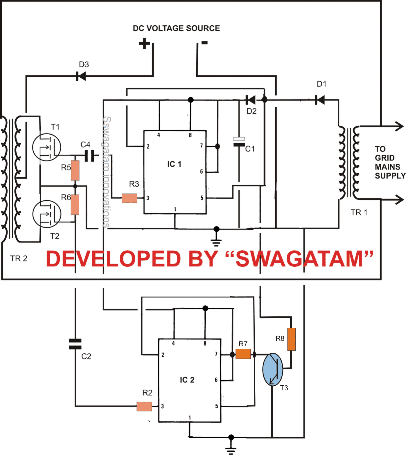
Referring to the circuit diagram, the IC1 and IC2 are basically wired up as a voltage synthesizer or in a more familiar terms a pulse position modulators.
A step down transformer TR1 is used here for supplying the required operating voltage to the IC circuit, and as well as for supplying the synchronization data to the IC, so that it can process the output in accordance with the grid parameters.
Pin#2 and pin#5 of the both the ICs are connected to the point after D1, and via T3 respectively, which provides the frequency count and amplitude data of the grid AC to the ICs respectively.
The above two information provided to the ICs prompts the ICs to modify their outputs at the respective pins in accordance with these information.
The result from the output translates this data into well optimized PWM voltage that's very much synchronized with the grid voltage.
IC1 is used for generating positive PWM, while IC2 produce negative PWMs, both work in tandem creating the required push pull effect over the mosfets.
The above voltages are fed to the respective mosfets, which effectively converts the above pattern into a high current fluctuating DC across the involved step up transformer input winding.
The output of the transformer converts the input into a perfectly synchronized AC, compatible with the existing grid AC.
While connecting the TR2 output with the grid, connect a 100 watt bulb in series with one of the wires. If the bulb glows, means the ACs are out of phase, reverse the connections immediately and now the bulb should stop glowing ensuring proper synchronization of the ACs.
You would also want to see this simplified Grid tie circuit design
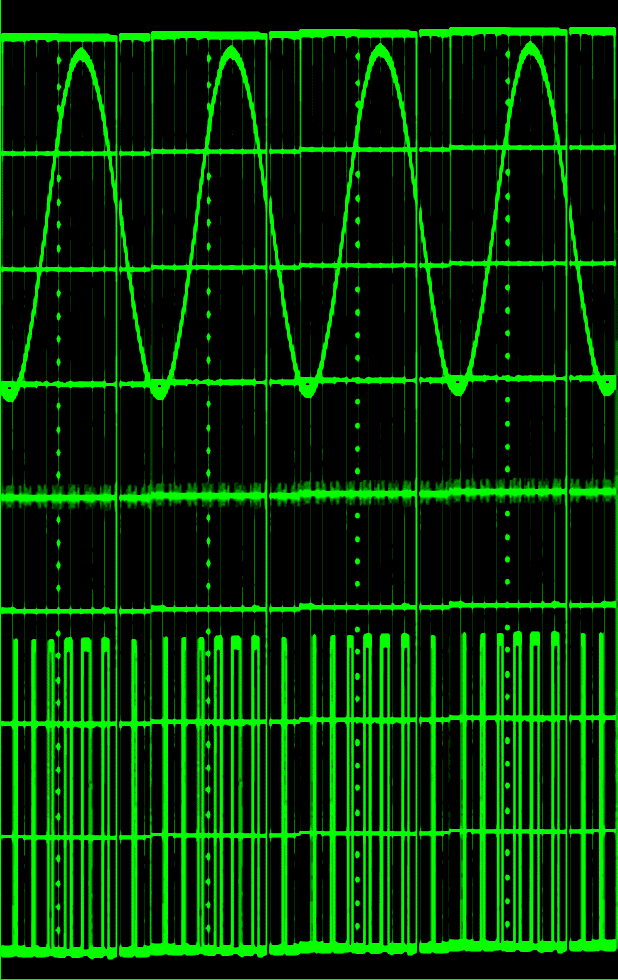
Assumed PWM Waveform (bottom trace) at the Outputs of the ICs
Parts List
All resistors = 2K2
C1 = 1000uF/25V
C2,C4 = 0.47uF
D1,D2 = 1N4007,
D3 = 10AMP,
IC1,2 = 555
MOSFETS = AS PER APPLICATION SPECS.
TR1 = 0-12V, 100mA
TR2 = AS PER APPLICATION SPECS
T3 = BC547
INPUT DC = AS PER APPLICATION SPECS.
WARNING: THE IDEA IS BASED SOLELY ON IMAGINATIVE SIMULATION, VIEWER DISCRETION IS STRICTLY ADVISED.
After receiving a corrective suggestion from one of the readers of this blog Mr. Darren and some contemplation, it revealed that the above circuit had many flaws and it wouldn't actually work practically.
The Revised Design
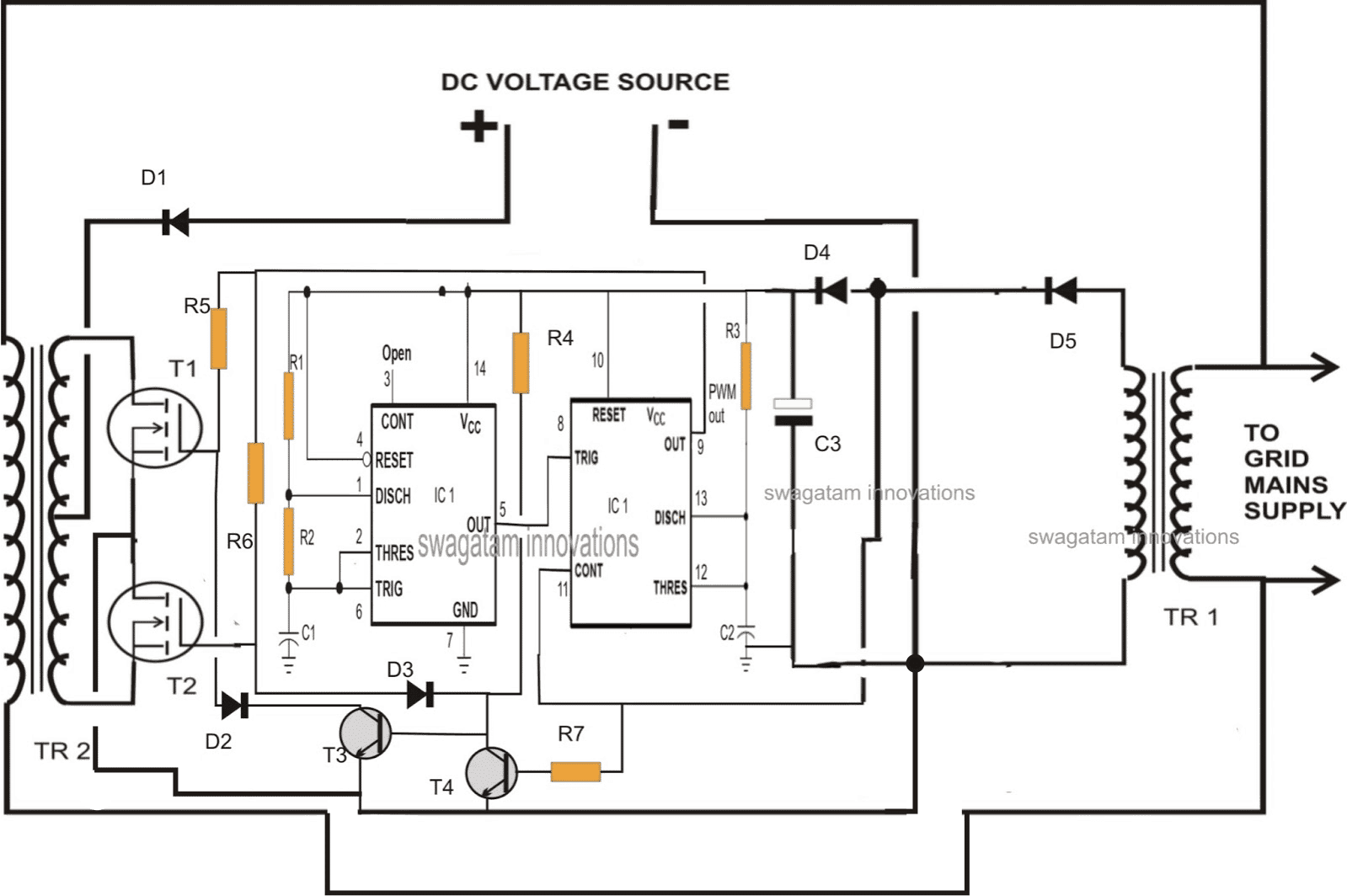
The revised design is shown below, which looks much better and a feasible idea.
Here a single IC 556 has been incorporated for creating the PWM pulses.
One half of the IC has been configured as the high frequency generator for feeding the other half IC which is rigged as a pulse width modulator.
The sample modulating frequency is derived from TR1 which provides the exact frequency data to the IC so that the PWM are perfectly dimensioned in accordance with the mains frequency.
The high frequency makes sure the output is able to chop the above modulation information to precision and provide the mosfets with an exact RMS equivalent of the grid mains.
Finally, the two transistors make sure that the mosfets never conduct together rather only one at a time, as per the mains 50 or 60 Hz oscillations.
Parts List
- R1,R2,C1 = select to create around 1 kHz frequency
- R3, R4,R5,R6 = 1K
- C2 = 1nF
- C3 = 100uF/25V
- D1 = 10 amp diode
- D2, D3, D4, D5 = 1N4007
- T1, T2 = as per requirement
- T3, T4 = BC547
- IC1 = IC 556
- TR1, TR2 = as suggested in the previous section design
The above circuit was analyzed by Mr. Selim and he found some interesting flaws in the circuit. The main flaw being the missing negative PWM pulses of the AC half cycles. The second fault was detected with the transistors which did not seem to isolate the switching of the two mosfets as per the fed 50 Hz rate.
The above idea was modified by Mr. Selim, here are the waveform details after the modifications. modifications:
Waveform Image:
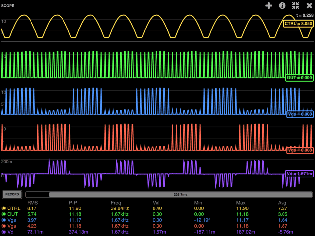
CTRL is the 100 Hz signal after the rectifier, OUT is from PWM from both halve waves, Vgs are the gate voltages of the FETs, Vd is the pickup on the secondary winding, which in sync with CTRL/2.
Disregard the frequencies as they are incorrect due low sampling speeds (else it gets too slow on the ipad). At higher sampling freqs (20Mhz) the PWM looks quite impressing.
To fix the duty cycle to 50% at around 9kHz, I had to put a diode in.
Regards,
Selim
Modifications
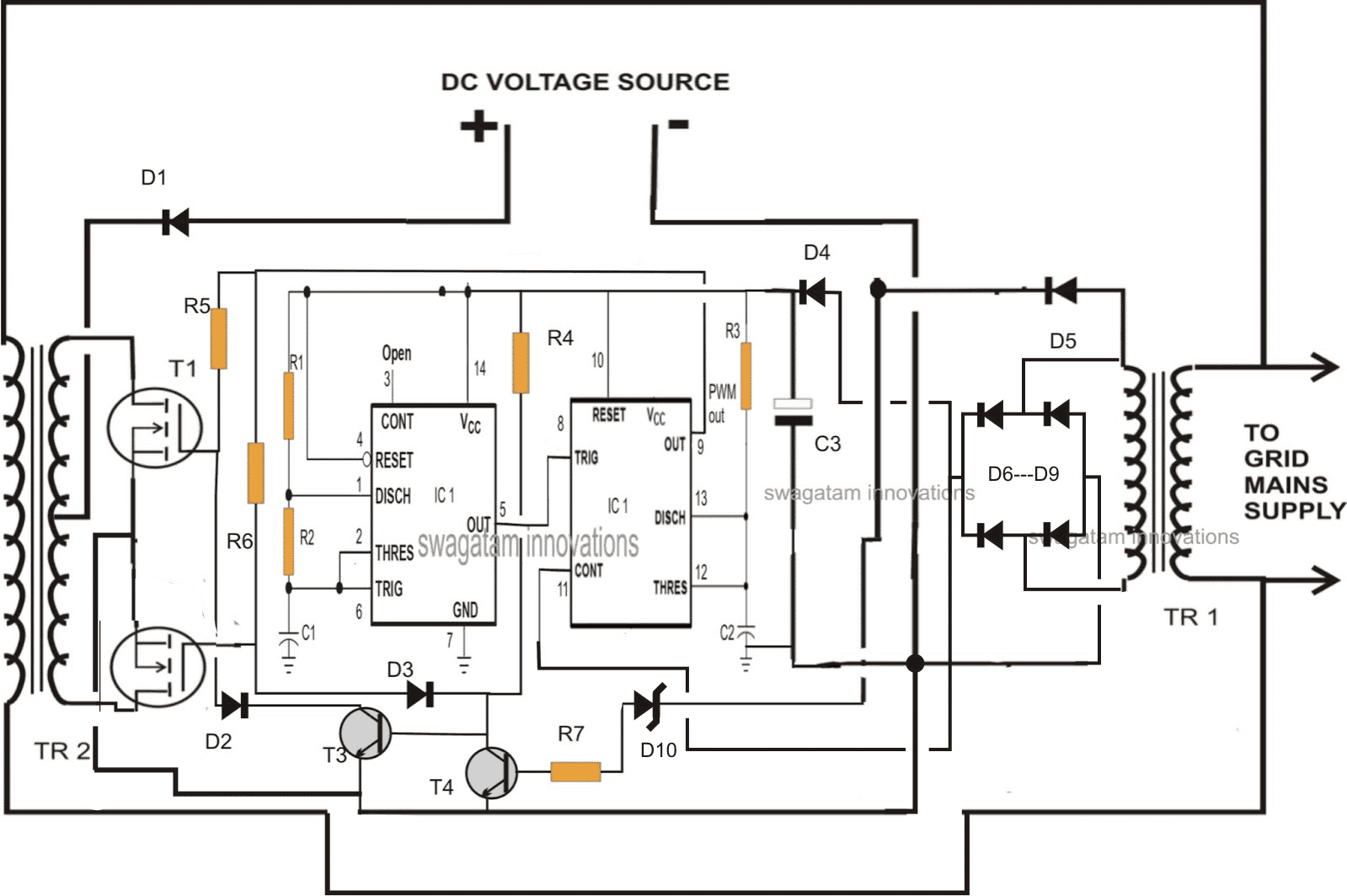
For enabling the detection of the negative half cycles, the control input of the IC must be fed with both the half cycles of the AC, this can be achieved by employing a bridge rectifier configuration.
Here's how the finalyzed circuit should look according to me.
The transistor base is now connected with a zener diode so that would hopefully enable the transistors to isolate the mosfet conduction such that they conduct alternately in response to the 50 Hz pulses at the base T4.
Recent Updates from Mr. Selim
Hello Swag,
I keep reading your blogs and continue experimenting on the breadboard.
I have tried the zener-diode approach (no-luck), CMOS gates and, much better, op-amps worked best. I've got 90VAC out of 5VDC and 170VAC from 9VDC at 50Hz, I believe it's in sync with the grid ( can't confirm as no oscilloscope). Btw the noise goes if you clamp it with a 0.15u cap. on the secondary coil.
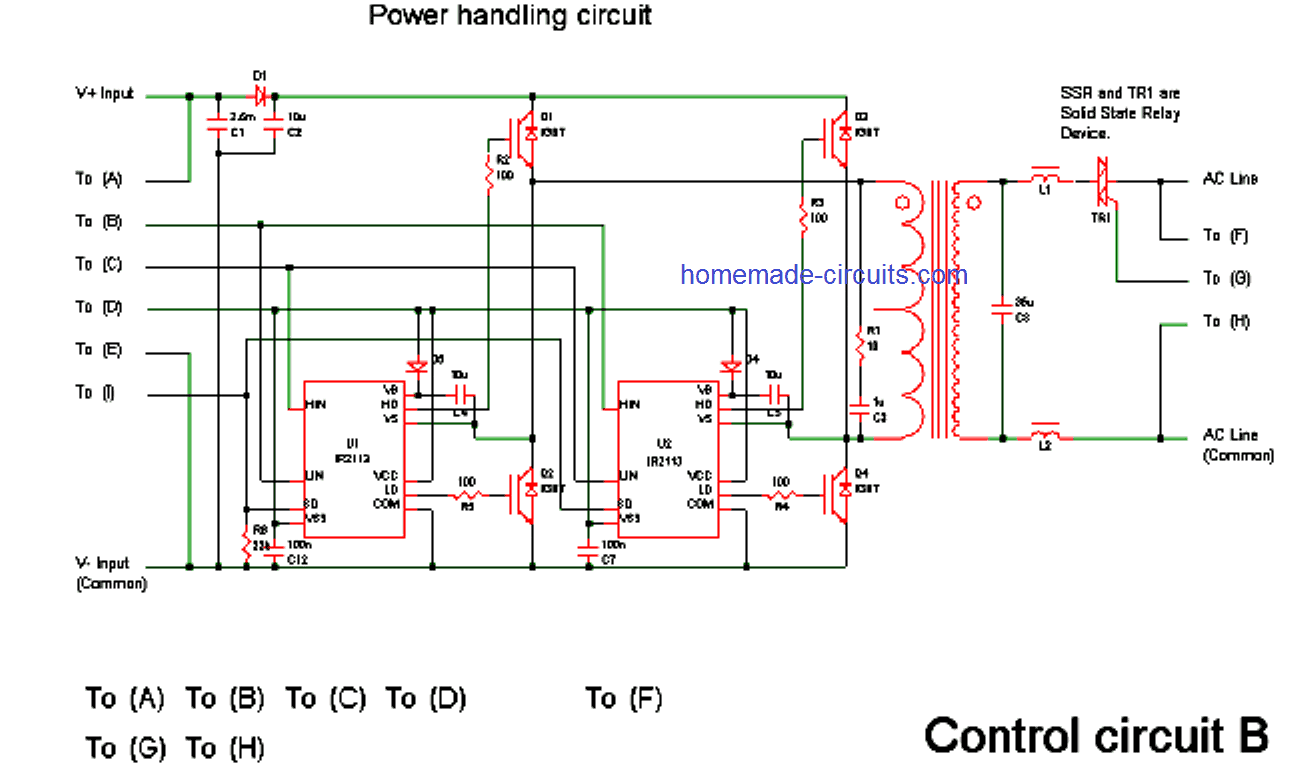
As soon as I put a load on the secondary coil, it's voltage drops to 0VAC with only a slight increase in input DC amps. The Mosfets don't even try to draw more amps. Perhaps some mosfet drivers like IR2113 (see below) could help?
Although in high spirits, I feel that PWM might not be as straight forward as hoped. It definitely is good to control torque on dc motors at low pwm freqs. However when the 50 Hz signal gets chopped at higher freq, it for some reason looses power or the PWMd mosfet can't deliver the needed high amps on the primary coil to keep the 220VAC going under load.
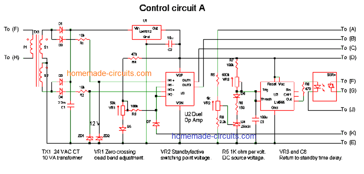
I've found another schematic which is very closely related to yours, except PWM. You might have seen this one before.
The link is on https://www(dot)electro-tech-online(dot)com/alternative-energy/105324-grid-tie-inverter-schematic-2-0-a.html
The power handling circuit is an H drive with IGBTs (we could use mosfets instead). It looks like it can deliver the power across.
It looks complicated but actually is not too bad, what do you think? I will try to simulate the control circuit and let you how it looks.
Regards,
Selim
Sent from my iPad
Further Modifications
Some very interesting modifications and information were provided by Miss Nuvem, one of the dedicated readers of this blog, I have explained them below:
Hello Mr. Swagatam,
I am Miss Nuvem and I'm working in a group that is building some of your circuits during an event about sustentable living in Brazil and Catalonia. You have to visit some day.
I've been simulating your Grid-Tie Inverter Circuit, and I'd like to suggest a couple of modifications to the last design that you had on your post.
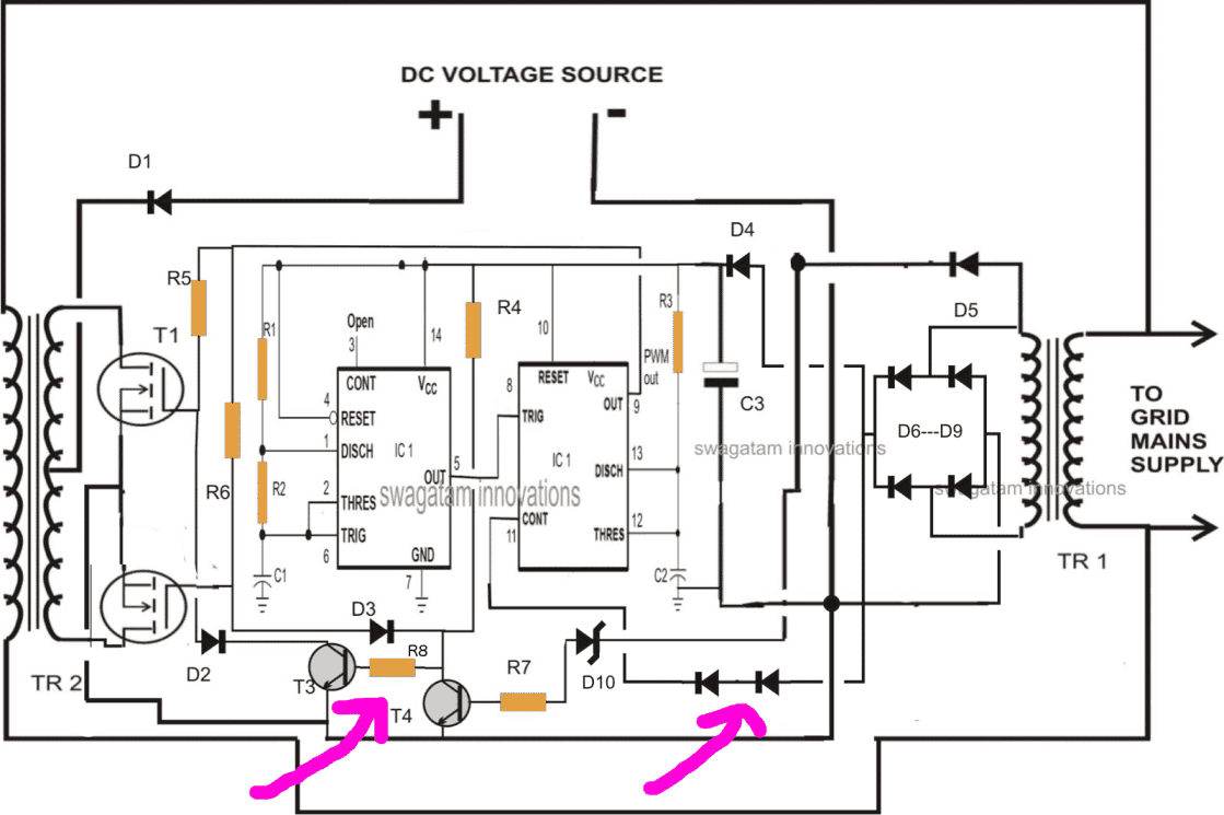
First, I was having problems where the PWM out signal (IC1 pin 9) would just blank out and stop oscillating. This was happening whenever the Control voltage at pin 11 would go higher than the Vcc voltage due to the drop across D4. My solution was to add two 1n4007 diodes in series between the rectifier and the control voltage. You might be able to get away with just one diode, but I am using two just to be safe.
Another problem I was having was with the Vgs for T1 and T2 not being very symmetric. T1 was fine, but T2 was not oscillating all the way up to Vcc values because whenever T3 was on, it was putting 0.7V across T4 instead of letting R6 pull up the voltage. I fixed this by putting a 4.7kohm resistor between T3 and T4. I think any value higher than that works, but I used 4.7kohm.
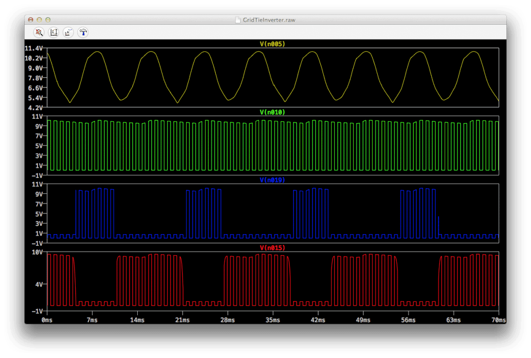
I hope this makes sense. I am attaching an image of the circuit with these modifications and the simulation results that I am getting with LTspice.
We'll be working on this and other circuits for the next week. We will keep you updated.
Warm regards.
Miss Nuvem
Waveform Images




Questions & Answers
Hi Mohini,
The second last circuit is the finalized design, but please note that it's only the concept which I have tried to produce, the person who intends to build it should have a sound knowledge regarding electronics and inverters, only then will he or she be able to implement the design correctly for practical feasibility.
If your not an expert in the field please don't even think of making such complex circuits, you will end up wasting a lot of money and time.
hi,i have solar panel 58v amorfni 128w 4 pieces do i go in serial 220v then adjust your circuit for it (220vdc) or do i make in paralel 4 x 58v then adjust your circuit for 58v what do you mean by that two cobination?
Hi,
the above design is yet to be verified, so I would recommend you to first test the second last design shown above, if it performs as per the expectations, you could go on upgrading it from there….
By the way, putting solar panels in series makes more sense and is always more efficient.
Hello Mr. Swagatam,
I am Miss Nuvem and I'm working in a group that is building some of your circuits during an event about sustentable living in Brazil and Catalonia. You have to visit some day.
I've been simulating your Grid-Tie Inverter Circuit, and I'd like to suggest a couple of modifications to the last design that you had on your post.
First, I was having problems where the PWM out signal (IC1 pin 9) would just blank out and stop oscillating. This was happening whenever the Control voltage at pin 11 would go higher than the Vcc voltage due to the drop across D4. My solution was to add two 1n4007 diodes in series between the rectifier and the control voltage. You might be able to get away with just one diode, but I am using two just to be safe.
Another problem I was having was with the Vgs for T1 and T2 not being very symmetric. T1 was fine, but T2 was not oscillating all the way up to Vcc values because whenever T3 was on, it was putting 0.7V across T4 instead of letting R6 pull up the voltage. I fixed this by putting a 4.7kohm resistor between T3 and T4. I think any value higher than that works, but I used 4.7kohm.
I hope this makes sense. I am attaching an image of the circuit with these modifications and the simulation results that I am getting with LTspice.
i.imgur.com/jkOoU8k.png
i.imgur.com/XpOsQKd.png
i.imgur.com/9uv0TGx.jpg
We'll be working on this and other circuits for the next week. We will keep you updated.
Warm regards.
Miss Nuvem
Dear Jose,
Changing inverter voltage specs would be difficult, you will have to dimension your windmill output as per the inverter requirements, may be by using a buck-boost circuit or other similar concept.
Hi Ryner,
since the involved current is varying from positive to negative every split second, if the two counterparts are not synchronized, would result in possible clashing of their opposite cycles in their AC phases which would in return result either in short circuiting of the power or one of the counterparts dragging the power toward lower levels thereby heating up the inverter devices.
That's why perfect synchronization becomes the ultimate crucial thing in GTI systems.
Hi Ryner,
Imaging putting batteries in parallel for increasing the backup time, yes, it's the current that is being added here.
If we increase the inverter voltage would load the inverter more than the AC mains input, so both counterparts must bear equal and uniform potential sharing.
Hi Ryner,
I have already taken care of and have correctly implemented waveform synchronization in the explained designs,
regarding other options I cannot say much, that will require further investigation.
I am doing my final year project with renewable energy, i prefer doing this circuit. I am doing it for a grid of 230V what must be my transformer TR2's ratings? Can i have the full final circuit?
Please help, Thank you in advance.
The final circuit is already updated in the above article. The concept was designed by me but is not yet tested practically, so pls be cautioned
TR2 wattage will be equal to the required power output from the inverter
How will this circuit behave to different voltages from the dc source, however its not a battery being connected to deliver a constant voltage?
the DC input could be from a battery or any regulated source. yes we'll have to add a comparator sensing stage for ensuring that the battery supply is cut off as soon as its voltage drops below the input DC ripple voltage from TR1 at pin#11 of the IC
Dear sir
In India THD,Freq,voltage all these thing at a time varries, then that how can adjust…if always less then 10 % thd…what is effect on perfomance..of GTI OR ONLOAD
Dear Dharamveer, if the DC input to the circuit is maintained at some constant, safe higher level say at 15V for a 12V system, the circuit will automatically take care of all the other factors associated with the mains supply (according to me)
dear sir
how can adjust GTI, THD, freq. voltage always varries….thd more then 5%
Sir, I need 10 Kw grid tied three phase solar inverter circuit diagram. If you have please send me on "ajinkya.brahma@gmail.com". If you have circuit giagram, please send me as early as possible.
Presently i don't have it, I'll try to find it…..
hi Swagatam Majumdar
can I connect directly to the solar dc source. can save a lot of costs.
but I have one problem, if larger loads feeds from tie circuit .circuit continues to operate or shut down
thanks
Hi Khang,
yes you can connect it directly to a solar panel, however the supply to the ICs must not exceed 15V.
The circuit output will follow the grid voltage proportionately…if the grid voltage drops so will the output from the inverter and vice versa…so with larger loads the output will adjust in accordance with the grid voltage.
hi Swagatam Majumdar
iI tested the circuit on the output voltage but only 4vac, f = 1kHz
I use fe core transformer (EI). transformer frequency more than. 100hz. perianth do fire transformer
can i change BC547 to 2N3904 ?
BC547 can be changed to 2N3904, ………cant troubleshoot without seeing practically.
hi Swagatam Majumdar
can you help me design and calcular an turbin wind capacity 200w.
thanks so much
hi khang, pls give complete specification in terms of voltage ad current.
Hi Swagatam Majumdar
i need technical specifications
U=24VAC
I=10A
V=0~10m/s (wind speed)
R=1m (radius)
do you need the technical specification of the motor??
hi Swagatam Majumdar
yes i want it.
choice and calcular :wire size(mm),round wire,magnet.
hi Swagatam Majumdar
my problem.
DC input 12v (power supply DC 3A)
transformer 12-0-12
i choice R1=100k,R2=20k,C1=10nF(~1khz)
output(pin 9 IC)=988hz,
current=0.01(DC IN)
output transformer=4VAC,frequency=100hz
Can you give me a guide
thanks
Khang, use a 6-0-6V transformer, you will get the required level of output……….but 4v is way too low… something may be wrong in your construction
hi Swagatam Majumdar
i send to you a picture result I measured.
have you address mail?
email is in the "contact" page, pls see it.
HI Swagatam Majumdar
I checked the construction .output transformer 200vac.I have a problem ,output frequency is not 50hz .it's >300hz.
can you give me a opinions
Hi khang,
I can't get the picture..please post all the details regarding what you are referring to and what exactly have you made so far.
ok i understood your point….connect a 1uF/400 cap at the output and then check the frequency, it will show 50Hz.
Hi Swagatam Majumdar
Have you received a picture yet.
I have checked output bulbs but no light .it's synchronization phase on grid.
thanks
Hi Khang, yes i have seen the pictures sent by you.
I think you should first make the inverter separately, make it to produce the required 220V, once it's confirmed you can proceed with the integrations.
Hi Swagatam Majumdar
I sent you that image on meter
you have received a picture?
Hi Khang, yes, I have seen it but could not interpret much…
Hi sir
I checked the device by connecting 1 100w bulbs .It's not light . circuits sync phase grid.can I connect on grid?
thank's
Hi khang,
something may be wrong in your circuit or you may be using a small battery/trafo…, try using a 12V 25ah battery and a 9-0-9/20amp transformer for getting a valid output
Hi sir
I'm using one 3A power supply and 1A tranfo 18-0-18 to check circuit.result check in meter
Thank's
for 18-0-18 trafo you will need 24V DC input……. and in that case the mosfet gates will need zener diode clamping for safety
hi sir
I'll check back
thank's,
Hi Swag
i have a question?
Why create 1kHz instead of 50 hz in output ?
khang, 1khz at pin14 of IC 4017 will produce 50Hz on the gates of the mosfets and from the trafo, that's how it works
Hi Sir
schematic diagram not ic 4017.
output pin 9 Ic 556 is 1khz.output tranfo 220v 1khz.can't I connect to grid?
OK sorry, i confused it with the other circuit…the frequency will is locked with grid frequency so it will be always 50Hz at the trafo output, the 1khz is for generating the PWMs, it's not relevant to the output frequency.
hi sir
saving bill
thanks so much.
hi Swaggatam, Quick question irfz44n will be ok with 12 0 12..yeah..im going to check if this gonna work. or have you any latest update on grid tie inverter. Thanks
Hi Barbe, yes IRF44n will work with 12-0-12 trafo.
Please proceed only if you have understood the concept well, and it's strongly recommended to do it in a stagewise manner
No I do not have any further updates regarding the above circuit, I would appreciate if anybody provides the test results of the same.
Sure…the only missing with me is the 68k i hope i can find this afternoon and try to blow in the evening..anyway i let you know once it work smoothly..also i found some diagram from the net but not sure with it…but too many blogs says it works???
OK, great!
Try only those which you understand and are able to simulate in mind, otherwise it could be a waste of money and time.
I try.. Its busted…any way its fine…im waiting for my scope..its hard to check all of this..!!! I will try your other design and let see we were going to blow that one aswell…i will inform you what ever i found…but this one…my 10amps transformer get hot aswell..its reallly busted.i want to follow only what is in the doagram to check if its actually working but i put all the nessisary precaution..!!!!
Hi Miss Nuvem,
Is your Project works…as currently I don't have the scope…with me? Thanks
Hi Mr. Swagatam,
What normally use transformer on TR2? can you please help me.
hi Swagatam
I have made such a design above. but I do not see the output of the R5 and R6 using osiloscop. and I have tried to synchronize between the inverter and generator 1 phase using a 30 watt lamp. I see there is a change from the original load dim lights become bright.
when there is no load voltage and frequency phenomenon after the sync is 220 volts to 210 volts and 50Hz be 49.5 Hz. but the mosfet is used even though I use a cooler heat. what should I do to reduce the heat? and what will not be a burden inverter generator?
Hi Agung,
Please refer to the following article, I have addressed the heating issue at the end of the article:
https://www.homemade-circuits.com/2013/08/homemade-100va-to-1000va-grid-tie.html
I want to ask you a schematic, for it is connected to the battery TR2 or mosfet?
Great job!… This idea can be extrapolated by the class "D" amplifier implementation with AC grid reference signal employing comercial ASIC!
Greetings from México
Thanks for the great suggestion! yes it could be feasible.
"The inverter should switch OFF instantly in case the grid voltage fails." Why Sir?
to make the Grid free from an AC mains potential which could otherwise kill or hurt an electrician who may be possibly at work across a faulty grid line without any caution, assuming the line to be switched OFF and safe.
hi swagatam.
i cannot find in your post. what zener diode should use. and how much power it could handle.?
Hi kikiloaw,
D10 in the last diagram can be a 6V zener diode, 1/2 watt rated
As I understand about the diagram. Any DC voltage can be a source. But depend on how many volts your MOSFET can handle right? And the transformer is depend also of how many power the your DC source can give right?
yes that's right….
as the mains voltage drops the inverter voltage also drops. when the inverter voltage drop. does it affect the power to be feed to the mains grid? and what is the efficiency of this inverter? and why does the tr2 only 6-0-6 ct?
I have only presented the concept only, it needs to be tested practically for all these answers
Hi Mr. Swagatam and Miss Nuvem,
Mr Swagatam a great design which was implemented by you. Miss Nuvem, is it possible that I can have the .asc file of your schematic? Because me too tried this in LTPice but output simulation was not as I expected. Thank you
Regards
Lovindu
You are welcome Lovindu, I hope Miss Nuvem will respond and fulfill your request.
By the way simulation softwares are never reliable and are no match to a human brain simulation…
Dear Sir,
Mr swagatam
good day.
My name is Zeal Njoku
i have been trying to have you in discussion, i am lover of electronics and i have bin going through your circuit designs so i picked interest on them. I must appreciate you for being so king and a generous man and having such time and giving people all this lectures, i say thanks to you.
I have some issues that i will like to discuss with you out of this site, i have some ideas that i brought up to ,my self about most inverter circuit which i want to try but i will like discuss it with you before i will start it then after i found possibility in it after practicing for success it can be post to your site and the explanation and diagram can be uploaded to your site so that all can see.
I will appreciate if you will send to me or type to me in my email address on zealthehightech@yahoo.co.uk so that we can discuss this issue at mail first before it can come up to this site.
Thanks as i waits to see your mail soonest.
zeathehightech@yahoo.co.uk
Dear Zeal,
I appreciate your interest, however due to lack of time and many comments pending it would be difficult for me to discuss through email.
So please feel free express your doubts here, I'll try to help
Okei meu amigo, eu gostaria de saber se você teria algum outro projeto a qual deveria tentar, pois não sou tão leigo no assunto, mas não tenho conseguido exito em minhas montagens em relações aos experimentos acima.??
Que tipo de projeto você prefere em relação a inversores ou qualquer outro simples, por favor secify a categoria que eu vou tentar ajudar
dear swagatam,
A great design which was implemented by you,i need a big help from you.I have dsp sine wave solar Hybrid inverter(offgrid) design and all.I want to convert my solar inverter in to bidirectional inverter.That means my inverter output 230v will be fed to ac grid.kindly help me
Thanks greens, it can be a little difficult,because to convert a normal inverter into a GTI would require modifying the internal circuitry of the unit and insert an external PWM to it with a duty cycle synchronized with the grid AC
Hi Swagatam continueing with Mr Green comment so which internal part of an off grid have to be modified for a GTI?
I half an ups and thought if I could use it's circuit for a GTI.
Thanks
Hi Aborg, the mosfet section of the uPS will need to be synchronized by appropriately tailoring its conduction rate with respect to the AC waveform…it will need to be done quite as shown in the second schematic from this article
https://www.homemade-circuits.com/2013/08/homemade-100va-to-1000va-grid-tie.html
Okey meu amigo. Gostaria somente de uma recomendação de vocês. Qual dos 3 projetos eu devo começar a construção. Abraço. Eletronica_cabrera@hotmail.com.
Você pode tentar o último projeto de circuito …. melhores desejos para você!
Okey assim que estiver concluido minha montagem venho aqui reportar… abraço Amigo
OK, claro
Dear Swagatam, I see you are very knowledgeable of electronics. I have a solar power system using APS brand microinverters, but every now and then there is a blackout in the middle of the day and I have to stop working at my computer. I would like to be able to generate a small amount of AC just for using a small inverter or ac generator in order to disconnect my home from the grid and tickle the microinverters into operating, as they react to the small generator. I would manually do the switching. Would the AC generated by the microinverters destroy the tickler source?
I work all day at my computer and it would be handy to be able to work at least during daytime, in case of a power outage.
Thank you dear Salvador,
you can try the following small UPS circuit that could be powered through a small 12V 7AH battery and used for the required purpose.
https://www.homemade-circuits.com/how-to-make-mini-homemade/
The design also a includes battery charger circuit for ensuring a safe charging for your battery.
The charger section can be replaced by any other suitable battery charger circuit as desired
IC555 ,Is really perfect for grid synchronization? let’s check and update you
hy Swagatam!
I have made this circuit.. I have got some issues.. I use 12v 5Ah battery.. my input voltage is 198VAc output of Tr2 is 156 VAc.. I use transformer 6-0-6 , 9-0-9, 12-0-12 all transformer gives hummm noise why this happen.. Ic1 get hot why??
Hi Muhammad,
It can be difficult for me to troubleshoot the voltage drop issue because it can happen due to a mismatched transformer specifications, or some internal inefficiency of the transformer.
The humming noise could be due to high modulation frequency from one of the Ics.
AS you may have understood that the SPWM synchronization is done by comparing the triangle waves and the sine wave from the grid. The frequency of the resultant SPWM will depend on the frequency the triangle waves. Therefore please adjust the frequency of the respective IC so that the frequency of the riangle waves are not more than 350Hz, this will create around 7 blocks on each SPWM waveform, and help to reduce noise in the transformer.
Also make sure add a resistor across gate/source of each mosfet, and also add reverse diodes across drain/source of each mosfet, this might prevent your IC from getting warmer.
Hy!
Sir my GTI gives 228v and my input volts are 203v.. is it synchronization or not? And if not what is the reason my voltages are more than Grid voltages??
Thanks
Muhammad, a multimeter might not give the right results always, you may have to confirm it with an oscilloscope, and check whether the peak and the RMS are equal or not.
hi,
sir i made the circuit of Grid tie inverter, i am facing the problems
First one is Mosfet T1 a (IRF 3315) gets heat up
the second problem is the output of transformer TR2 is 156V-165V, and transformer gives noise
sir how can i resolve these ?
whenever i check the Current with DMM across the transformer it gets heat up ,, what can be the cause of this heating
sir one more thing
how one can predict about synchronization without oscilloscope, how will i come to know that my Grid tie inverter circuit is doing correct synchronization
Hi Rida,
please see the explanation which I provided to Muhammad Imran Akbar, your question looks similar to his.
If you are checking the output current by directly connecting an ammeter then that might create a momentary short circuit at the transformer secondary, causing some heating up of the transformer… so that’s normal.
Synchronization can be confirmed by checking and comparing the RMS from the inverter transformer output and the grid mains, they must match each other. You may use a variac and change the grid input to the GTI, this must proportionately change the output from the inverter transformer also…these tests will confirm that your inverter output is correctly synchronized with the grid voltage
sir for 12v , 5Ah battery in GTI
what can be the rating of transformer can i use 6-0-6 10A transformer
yes you can try that.
Sir I successfully made the GTI circuit,but still their are some problems,,
Input
v=201v
F= 50hz
But at the output of my GTI circuit I am getting
V= 208v
F=48.9Hz
There is slightly difference between input and output.. At start the frequency at output of GTI is 51.8Hz but after sometime as transformer gets heat up the frequency goes down to 48.5Hz to 50.2Hz
But when I connect load at output of GTI the load does not work,,
Why my bulb is not glowing at output?
Sir kindly tell me the problem how can I trouble shoot it?
Rida, the voltage difference is due to harmonics which could be wrongly interpreted by a digital multimeter. An oscilloscope will be able to tell you correctly whether the syncing is working or not.
If a load is not working that means the power transistors are not pumping the required amount of current into the transformer, or the transformer is very low with its amp spces, or the battery is not good…any of these could result in a weak output. Please let me know the correct specifications of the power devices, transformer, and the battery, I’ll try to troubleshoot.
Sir the Mosfet i had used are IRF 540, and IRF 3315 both are same, i had varified,,
And the transformer rating of 6-0-6 is 200mA (if i use transformer of high rating it drops voltage at output)
And battery rating 12v, 5Ah
Can you share with me any Gmail account of yours or whatsapp no i will share with u pictures of my circuit
Rida, 6-0-6V 200mA will give an output of 6 x 0.2 = 1.2 watts, so if you use a 1 watt/220V load then it might work, if you want higher load to work then you must use higher transformer.
The battery is also very small, it must be at least 12V 7Ah, and the transformer should be 6-0-6/10 amps to for any useful results.
Also the 6-0-6V may not be necessarily correct, it must be selected as per the average voltage value that may be available at the output pins of the IC 4017. If it’s 6V then the transformer could 6-0-6, if it is 7V then the transformer could e 7-0-7V an so on.
Thanks sir,
I am making a prototype mini project
Anyhow thanks it helped me much
You are most welcome Rida!
Sir the difference between output and input voltages is 10v? It can be fatal or not?
And the frequency at output vary from 49Hz to 51Hz?
Moreover i had checked the phase sequence by connecting a bulb between the output and input phase, the bulb glow very dim at both phases,, what can be the cause of this? This is not the scenario that bulb glows at both phases
Kindly guide me more
Sir the voltage at output pin of IC(TIMER) IS 5.47V
AND I AM USING 6-0-6 transformer!!
Will it be fine?