Are you looking for free circuit diagrams, project ideas, and solutions? Are you interested in getting personalized help with an electronics project you're having trouble with?
Feel absolutely free to contact me through the comment box below the articles for getting quick solutions to your queries. I'll try my best to get it done for you absolutely FREE!
For submitting schematics or circuit diagrams you can send them to the following emails addresses.
Email ID
homemadecircuits @ gmail.com
+91 8 7 7 9 6 7 6 1 9 2
Work Address

Questions & Answers
Hello-
I enjoy your website very much and have come across it a few times and so finally I have subscribed.
Something that has interested me over the years is the Tesla pancake coil. It has all kinds of unique features and uses but the one that I like best is the supposed overunity capability of this coil. Some say if you find and use the resonate frequency of a pancake coil then more power will come out than went in. Ya, not supposed to happen right? There are more than a couple of people on the internet who demonstrate that effect or at least seem to.
So I am sure you have heard of it too and I am wondering what your thoughts about it is or perhaps you have already experimented with these interesting coils?
Thanks in advance!
Hello Pierre, Thanks for subscribing and for the kind words!
The Tesla pancake coil is an amazing piece of engineering. Its flat spiral design maximizes internal capacitance, allowing it to achieve resonance perfectly.
Regarding overunity, when a coil hits its resonant frequency, then circuit’s impedance drops and a huge amounts of energy circulates inside it. This high circulating energy often creates the illusion of radiant energy on meters or oscilloscopes.
However it is just storing and shifting energy highly efficiently. The total power coming out will never exceed what goes in…..so the law of conservation of energy still holds firm… Those videos online are usually getting confused high-efficiency reactive power with overunity.
Its a fantastic circuit to experiment with for wireless power transfer, but it doesn’t break the laws of physics.
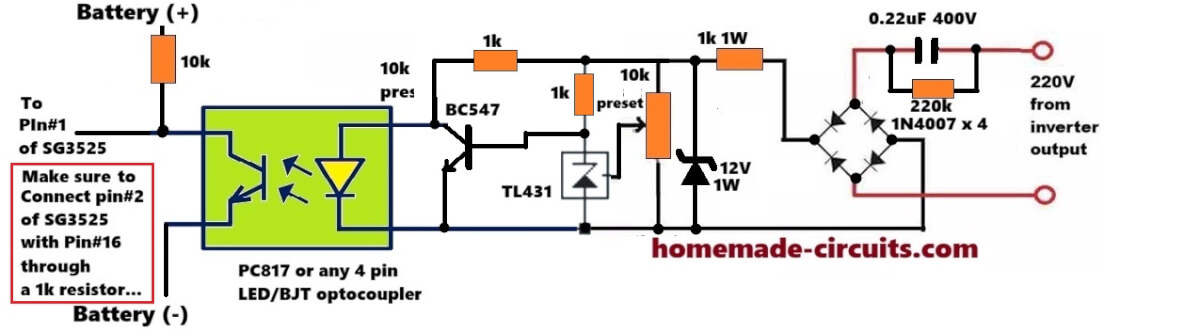
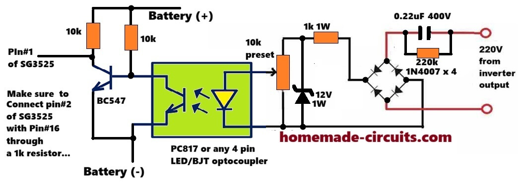
Hello I’m trying to build feedback for SG3525 with octocoupler and TL431 with variable resistor how do I connect this to my high voltage side there’s no auxiliary output just direct 300v
Using TL431, you can try this concept:
Hi, you can adopt this circuit for your application, however i did not use a TL431:
hi engineer
How can I learn electronics step by step on your site?
Hey Isa,
You can learn by asking me specific questions regarding the posted circuit ideas, on this website and I will try to answer them to you and help you to learn more…
sir how are you ineed temperature circuit diagram and humidity circuit
Abdul, you can get all the information on this page:
https://www.homemade-circuits.com/?s=temperature+humidity
Looking for a charge controller circuit for a wind turbine. Input 300Volts 7 amps output required is for two 300 amphr batteries connected in series.
Thanks I will try this out immediately
What is the battery voltage?
2 X 12 Lead acid batteries in series 24 volts for charging voltage should be around 32 volts
So you need a 300V to 32V DC to DC converter.
The power will be input 300 * 7= 2100 watts , and output current will be 2100 / 32 = around 60 amps.
For this you will need a buck converter circuit which you can easily design using the following calculator:
https://www.homemade-circuits.com/buck-converter-calculator/
Hi, I am looking for help with an automotive transmission controller. I would like to use a momentary button to control a contact/switch that would stay open when the button is pushed and stay closed when pushed again. The momentary button side would be 12v but the contact/trans controller side would be completely separate and see no power or ground. It functions based off of going from open to closed or closed to open. It can start off in the open position being off, close the circuit and it turns on, if not manually turned off by opening the circuit there is and auto off at low speed that occurs, this would leave the trans in off position with the circuit closed, you would then have to open the circuit to turn back on.
Hi, you can simply do it with 4017 IC circuit and an SSR. However the contact switch would need a separate power supply to operate…
Dear Swagatam,
I have been following your website as a hobbyist. i just want to make diy small washing machine about 3 to 4kg load with 12v or 230v ac. can you please advice me the motor and bi directional timer with pause
Thank you dear Prasad, I appreciate your interest very much.
It can be easily done using an IC 555 and IC 4017.
I will design it soon and let you know…
thank you Mr.swagatam. I will be happy to receive the same
No problem Prasad, you can try the following circuit
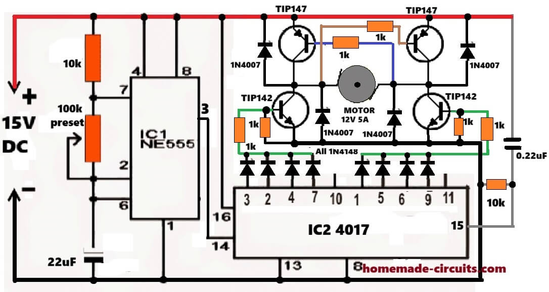
can you please explain the diagram. And also substitute for transistors if any
Prasad, I have explained the full circuit in this post, please check it out:
https://www.homemade-circuits.com/make-this-simple-washing-machine/
Trying to use a LM2577-ADJ with 5v input from USB and to get 60v output.
I just cannot get any higher than 56.6v on my Fluke 77 multimeter, but my FNIRSI oscilloscope 1014D shows 59v. Not sure about that?
The R1/R2 ratio is set to R1=100k and R2=2.09k
Input cap = 100uF and output cap = 1000uF and inductor = 330uH
Schematic is based up https://www.ti.com/lit/ds/symlink/lm2577.pdf page 2. Tried different values for in and out elec caps, inductor and resistor ratio, and different diodes.
Any advice or have I just hit the limit on its output, with maybe an out-of-spec IC.
The output voltage you are seeing is quite normal for this configuration. Eventhough the resistor ratio correctly sets the output for 60V, yet boosting 5V up to 60V requires a very high duty cycle, close to the practical limit of the LM2577 IC.
Due to internal losses, switch saturation, diode drop, and efficiency limitations the IC typically cannot reach the exact theoretical value at such a high step-up ratio. So, an output around 56V to 58V is expected.
The difference between your multimeter and oscilloscope readings is also normal. The multimeter reads the average DC voltage while the oscilloscope displays peak voltage including ripple causing the higher reading on the scope.
Also if the circuit is powered from a USB source, then available input current may be limiting the output voltage further.
So in all your circuit appears to be functioning correctly and you are most likely observing the practical upper limit of the IC rather than a fault.
Many thanks Swagatam for a quick response.
I have come across similar problems with stated max values in datasheets, which is a bit misleading. This is something like 8% less than stated (theoretical value).
I will try a few changes to confirm practical limits.
1 – Revert back to the minimist component count and values.
2 – Check oscilloscope display settings for peak readings or whatever (V_pp, V_p, V_max, V_min,_avg, V_rms)
3 – Try using a more powerful 5v supply source.
Thank you Gray, for your understanding, sure, you can try those steps and let me know how it goes….please feel free too ask if you have any further doubts or questions..
Hi Swagatam – just an update
3 – tried using bench power supply for 5v supply with more Oomph, but that did not have any effect.
1&2 – In reverting back to original components. I removed 100uF across input, with just 0.2uF as smoothing on input. This had no effect.
This is where it gets interesting, as I removed all of the output smoothing capacitors (1000uF elec and 1uF ceramic).
In checking the output, I was somewhat surprised in getting the following waveform (sorry about file size) http://www.gb-online.co.uk/dump/LM2577-resized-20260504_103001.mp4
The Vpk is 95V dc coupled. The LM2577-ADJ was burning very hot, as it obviously did not like running above the 60v max with no output caps.
I should have put a 680uF across the output.
Got to wait for a replacement chip, and also change the 330uH for a 100uH
Hi Gray,
That waveform now explains the situation very clearly.
Once the output capacitors were removed, the boost converter output was no longer being filtered or averaged into a steady DC level. What you are now seeing on the oscilloscope are mainly the raw switching spikes and flyback energy pulses coming from the inductor, which is why the peak voltage is shooting up close to 95V.
Under this condition the LM2577 feedback loop also becomes unstable because it expects a reasonably smooth DC output for proper regulation. Without the output capacitor, the IC can momentarily overshoot far beyond the intended output voltage, causing excessive stress and heating of the internal switch transistor. So the overheating you observed is expected.
The output capacitor in a boost converter is actually a very critical part of the regulation system, not just a smoothing component. It stores the transferred energy between switching cycles and keeps the feedback loop stable.
A 680uF or 1000uF output capacitor should definitely be restored before further testing. Also, changing the inductor from 330uH to around 100uH may help improve the switching behavior for this application, especially at the high duty cycle required for stepping 5V up to 60V.
Hi Swagatam – We have reverted back to the Texas schematic with 100uH and output cap being 680uF but with the input cap only being 0.2uf (no elec cap).
Got the Vpk to be 59.5V and a ripple of about 600mV.
We did have to alter the R1 and R2 ratio as the resistors were way out of tolerance.
Going to next have a go at using LM358 + mosfet and multiple TIP32 for a 60V 30A power supply
So many thanks for listening to me.
Thank you Gray, for updating the results.
Sounds great! however LM358 + mosfet and multiple TIP32 looks like a linear regulator which will heat up a lot.
Instead why not design you own buck converter using the following tool:
https://www.homemade-circuits.com/buck-converter-calculator/
Is there a similar tool for Boost converter ?? Thanks
Yes, for boost converter you can try this tool:
https://www.homemade-circuits.com/ic-555-boost-converter-calculator/
Respected Sir,
I am interested in the circuit which track and remember the over and under voltage, the number of times it exceeds or goes low in 24 hours with memory.
I got totally confused with the products available on net/ amazon or other sites.
Please suggest something.
Mains over and under voltage tracking system
Hello Dhananjay, it is actually very easy.
You just need one LM393 IC and configure its one comparator to sense the high voltage, and configure the other comparator to sense the low voltage level.
Under both the conditions, the respective comparator outputs become high. These number of highs from the comparator outputs are fed to two separate digital counter circuits which display and record these ups and downs of the mains voltage.
You will need a battery backup for this circuit, to ensure the circuit memorizes the results even if the mains supply fails.
Respected Sir,
Thanks for your response and the valuable ideas.
Sir, since I don’t have sufficient time to get through the complex circuit and design the diagram, can you please share some assured readily available circuit boards in market.
Thank you Dhananjay, you can buy 4 separate modules, as given below.
1) 1no adjustable High voltage detector module.
2) 1no adjustable low voltage detector module.
3) 2nos digital counter circuits.
and now join these modules together as explained by me in the previous comment…
Hello Swag,
I kindly sent you a message on email and on facebook in case you didnt see it. But i think you blocked me, that is unfortunate. We genuinely needed your advice and help with our project.
I hope you understand that it is a legit request, and not spam.
Best
Rob (Bob Hein)
Hi Rob,
I never block any of my genuine readers.
I saw your email and have already replied to it.
Please check your email inbox…
All the best t you!
Sir swag, do you have any suggestion, on how to put an early warning device in a blind tunnel to avoid collision of two vehicles coming in two opposite direction?
the idea is to send signal to the other end of the tunnel not to enter the tunnel because there is someone already in the tunnel coming from the opposite direction…
the blind tunnel I was talking about is at least 500 o 700 meters long…there is no concern if the we’re riding on a motorcycle, the traffic can come from both directions… but for a 4-wheels, it’s a different stories, the tunnel turn into a one lane passageway….
Thanks Sir Swag, hoping you help us find a practical solutions, in favor of our community….
Thank you Cindy, for your interesting query.
I think that can be perhaps solved by installing vibration detectors on the railway tracks on both ends of the tunnel. If any one of the trains comes near the mouth of the tunnel, the indicator on the other end of the tunnel is activated, and vice versa happens when a train approaches the other mouth of the tunnel.
I hope it makes sense?
Yes Sir, that’s the idea…. but is it possible that both end of the tunnel well be aware of the actual location or distance of the vehicle moving inside the tunnel?….
can it be done with just a simple circuit….. and not a complicated one Sir?
Yes, I understand what you are trying to achieve, however, detecting actual location and distance can make the circuit quite complex. The vibration detection concept can be implemented very easily and effectively.
Hi Sir Swag, can you show me the circuit that detect vibration and guide me how the circuit works and it’s components…. thanks
Thanks Cindy, the vibration sensor will need to be installed inside the soils under the railway tracks, and the transmitter installed above the ground, on a pole for sending and receiving the signals….if possible I will try to do it soon…
thanks in advance Sir Swag, hoping that all the necessary components in your circuit are all available here in my location… can’t wait to build your circuit Sir🙂
Thanks Cindy,
You can start by building the following circuit first:
https://www.homemade-circuits.com/footsteps-detector-circuit/
If you succeed with the intended results then we can proceed with the integration of the transmitter section and receiver section.
hi Sir, just to clarify some component in the circuit:
IC3 in the circuit figures is IC 7555 but you mentioned it as IC 555, is it the same? also the loudspeaker is 70 ohms impedance, very rare value in my area Sir, common speaker available for us here are 2ohms, 4ohms, 8ohms only…or maybe i misunderstood everything Sir, please enlightened me, thanks
Hi Cindy, IC3 is 7555 which is the CMOS version of a standard 555 IC, meaning it can work with 3V also and with much lower currents. The speaker is not required, because we want to trigger a transmitter with the output, not a speaker…
If you are finding this circuit complex, you can try the following design instead:
https://www.homemade-circuits.com/sound-activated-led-lamp-circuit/
Hi Sir swag, any best possible replacement or equivalent for TL081 IC and OA90 DIODE, thanks
Hi Cindy, you can try TL071CP, LF351, OPA134PA…
or even uA741 might work…
Good morning Swagatam,
My name is Dorian, I am in need of some assistance with building two AC supply sources. I have a darkroom, I use an Omega Super Dichro enlarger. There are three different output voltages 120Vac, 6.3 Vac and 39.4 V ac. I would prefer the option to build two supplies that are variable to adjust for the 6.3 and 39.4. The transformer power supply, (Omega Chromacontrol) which includes the timer is severely arcing. I would like to have the transformer rebuilt, I can not find a source. I decided to take a different approach. I do not need the timer. I need to supply the enlarger head with the above mentioned voltages (measured at the supply). No where can I find schematics for building AC to AC. Just for information, I have a degree in Electrical Engineering, spent 30 years in avionics, I have lab experience. Much appreciated.
Good Morning Dorian,
Instead of trying to design an AC-to-AC electronic converter, I would recommend the simpler way to use two separate transformers, because that usually stays more reliable and there is less trouble later.
For Supply 1, which is for 6.3 Vac adjustable, we can use a transformer with 120 Vac on the primary side, then the secondary can be 6 Vac or 7.5 Vac, depending on what is available.
Power rating can be around 1 A and if the lamp current is not known higher, then this usually remains enough.
If exact 6.3 Vac is needed then we can add a small series resistor or maybe trim it a little through a variac, to bring it closer.
Now for Supply 2, which is 39.4 Vac adjustable, again primary stays 120 Vac but secondary can be 36 Vac with some trim adjustment, or directly 40 Vac if that type is available.
Power rating here depends fully on enlarger lamp current, so unless that current is known, then exact transformer size can not be fixed.
Since 39.4 Vac is not a common value, then easiest way is usually 36 Vac transformer with a small buck or boost trim winding.
Or we can use two secondaries, 24 Vac and 15 Vac and connect them in series.
That gives 24 + 15 = 39 Vac, so now it comes very near the required value.
Hello, I can’t do anything with the diagram, can you help me?Adjustable SMPS circuit 0-100 V 50 A
I will try to get a simpler design, if possible…
Hello from Italy, Swagatam!
For my motorbike I would need two circuits i’m unable to find anywhere… maybe I’m missing the right keywords, but right now I have no solution.
1) I would need a 12V stabilizer: i’ve put LED lamps on my bike, and also a DRL light, but they filckers a lot (the less power the bike uses -it has heated handgrip and seat- the more they flickers). So a Motorbike/Car 12V stabilizer, able to handle the power for two low/high beam LED lamps could be very useful.
2) on the Kawasaki of my son there’s such device, so his lamps go ON only when the engine is running, not just with the key switch.
Here’s the schematic: https://imgur.com/yQL2XCu
and here the detail: https://imgur.com/IF1vyWz
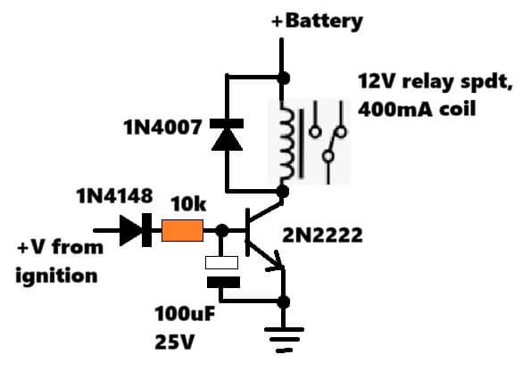
I don’t understand how it works, but I could use a relay that goes on only after the engine runs (maybe even delayed by a pair of second) so I could power some circuit not just by turning the key.
Thanks!
Hi Parduz,
for the stabilizer circuit I would recommend using a boost converter circuit such as the following one:
https://www.homemade-circuits.com/xl3608-5v-9v12v-dc-2-amp-boost-converter-module/
Make sure to put a large capacitor such as 6800uF/50V across the output terminals of the converter…
For the kawasaki bike, you can try adding the following relay circuit, and check how it works:
Thanks.
About 2) I’ve drawed it in the Circuit Simulator:
https://imgur.com/a/P9bfG7e
Have I understood you well?
How can the relay retains itself once it switch on? To avoid fast switching if the engine have problem starting or chokes?
Your diagram is correct.
However, the relay will not remain latched in this diagram, if the engine stops or halts.
If you want the relay to remain latched, you will need to replace the BC547 transistor with an SCR C106.
BC547 base will replace with SCR gate, collector with anode, and emitter with cathode.
I previously found this power supply design on homemade-circuits.com.
I do not see it on the site any longer.
I do not remember the output specs.
I need something similar using the 2n3055 that will output up to 50vdc 10amp with overcurrent protection with led and audible warning.
Thanks for your interest, It is still there, here’s the article link:
https://www.homemade-circuits.com/0-to-50v-0-to10amp-variable-dual-power/
i need your help with 3000kw sinewave inverter here it’s failing
Please give more information…
Hi, Swagatam,
There are light sensing circuit and darkness sensing circuits using LDR all over the internet.
Is there a schematic on your site when both of them combined together?
Idea behind it is: when light level drops below predetermined level – LED comes on ( saying “Too dark”) , when light level gets above certain level – another LED comes on (saying “Too bright”). Levels could be adjusted with 2 different potentiometers, to have some hysteresis.
Do you ever come across such a schematic? It could be a good idea for your next tutorial.
Best regards, Michael
Hi Michael,
I think you can customize the circuit explained in the following article.
https://www.homemade-circuits.com/how-to-build-dual-solar-tracker-system/
You can eliminate the transistor bridge stage and connect the LEDs directly from the opamp output to ground with 1k series resistors…
Thank you, Swagatam,
I will look into the schematic. Want to have just one LDR and LM339 as a comparator.
https://www.homemade-circuits.com/how-to-make-ic-lm339-circuits/
Best regards, Michael
Yes, actually it can be designed using a single LDR and two comparators….let me know if you need any further help!!
Hi,
Re:Simple Function Generator Circuit using IC 556
According to the diagram IC 556 is showing with 8 pins however IC NE556 has 14 pins.
Thank you
Hey Walter, can you please comment under that same article, then I will be able to quickly refer to the diagram and answer your question…
Hey Swagatam, thank you for quick response. Diagram: Simple Function Generator circuit using IC 556 on the diagram is showing IC1 556 and power supply is applied to the pin 8 – + 9V.. According to Digi-Key and NTE INC CROSS REFERENCE IC NE556 has 14 pins and the power supply is applying to the pin 14 not 8. Because IC 556 doesn’t exist with 8 pins. Thank you.
OK thanks got it, that IC is supposed to be the IC 566 and not IC 556 as mistakenly shown in the article…
however I have now replaced it with the following diagram using IC 555….which makes more sense now:
Thank you Swagatam, 555 timer makes more sense. Have a great day. Walter
You are welcome Walter, have a great weekend… let me know if you have any issues with the circuit…
Swagatam DA,
Can we make an AC energy saver like Airtron. https://greenco.in/casestudy/Technical%20Bulletin%20No%205%20%20-%20Energy%20Savers%20For%20Air%20Conditioners%20%20%20%20%20%20%20%20%20%20%20%20%20%20%20%20%20%20%20%20%20%20%20%20%20%20%20%20%20%20.pdf
The unit is very expensive. we can make it easily with Arduino and a temperature sensor. That will affordable for everyone. Please check the scope.
Thanks Abhirup,
It looks interesting but we do not know about the algorithm….if possible I will try to crack it and let you know…
Hi Swagatam. I’ve been following you for many years. I have two water pump motors, and a second one as a spare. They are activated by a pressure switch. I want them to operate sequentially each time a signal comes from the pressure switch. This way, both motors will wear out equally. Do you have any circuit recommendations? Thank you very much.
Thank you Ismail,
I guess you want to operate the motors alternately so that they share the load operation equally, and both the motors get prolonged life, and wear out uniformly.
In that case I think you can try the following concept:
https://www.homemade-circuits.com/alternate-switching-relay-timer-circuit/
For triggering the circuit through a pressure switch, you can connect an SCR between the positive terminal and the pin#4 of the IC, with pin#4 also connected to ground through a 10k resistor.
Next, the gate of the SCR can be configured to sense the trigger voltage through a suitable resistive divider network.
Sorry, I think I misinterpreted the question, the above concept will toggle the motors continuously on each triggering, which is not good….you want the motors to toggle sequentially, for alternate sensor triggering. In that case, the following 4017 IC would be a better option.
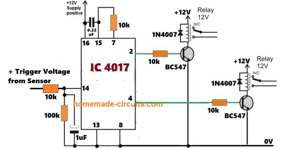
I built the circuit, but it didn’t work. I can’t see any voltage across the 10k resistor on pin 14. What voltage is required for triggering?
That means the voltage from your pressure sensor is too small, you need minimum 5V at pin#14….. please check it separately and let me know how much voltage are you getting from the pressure sensor output…then I will suggest the required modifications…
Thank you very much, sir. I will try it as soon as possible. Greetings from Turkey.
You are welcome Ismail….
I replaced the 4017. There’s a gap in the timing belt transitions, as you can see in the video. It would be great if a relay activated with each timing signal.https://youtube.com/shorts/aVRog1_bwaM?si=5pOgRgnvTpT3QUYX
OK Understood! you do not want the switch off action for the motors after each sequence is completed.
In that case please do the following modifications in your existing circuit.
Replace pin#4 connection with pin#3
Replace pin#7 connection with pin#4
Pin#7 can remain open and disconnected.
Hello swagatam,
I’ve been looking at the Korg Volca Nubass and more specifically its supposed “vacuum tube VCO”. This really intrigues me but I was unable to find any available schematics or information on how this was done and I was wondering if you knew. Thank you!
Hi Emerson,
actually this “vacuum tube VCO” thing in Volca Nubass is not like those big old glass tubes we see in vintage synths or guitar amps, not that type. Korg Volca Nubass is using this small thing called Nutube, it is actually a real vacuum tube only but very tiny and low power, so it can run inside this small Volca box without heating or high voltage drama.
Now the company never released schematics, so nobody outside really knows the exact circuit but from what Korg itself says and from people who opened it, the tube is sitting in the oscillator sound path and also in the sub bass and drive part. So the oscillator is analog but the Nutube is there to add that tube like uneven harmonic feeling, not some fake digital effect.
So yes, it is a real vacuum tube, but done in modern style, not old school tube VCO like 1970 lab equipment, more like clever compact tube flavor added into an analog synth.
That’s so cool thanks for sharing.
Thanks, glad you liked it….
Hey Swagatam, I’m a big fan of your website and your audio circuits.I was wondering if you could help me out with a project Idea I have. I’m trying to make an analog pitch shifter guitar pedal with two pots. One pot goes from an octave lower than the sound source to an octave higher than the sound source, and the second is the ability to blend the original signal and the modulated signal. I’m not sure doable this is but I thought I’d reach out anyway in case you were able to make a schematic for this. Thank you!
Hey Emerson, thank you very much for liking my website and audio circuits.
About your idea, I must say that proper analog pitch shifter which can smoothly go from one octave down to one octave up using a pot, is not really possible with simple analog circuits. Pitch shifting needs time stretching and compressing of the signal which is why most good pitch shifters are digital.
With analog circuits, we can do octave down and octave up effects separately, using rectifiers, dividers or bucket brigade ICs but the sound will be rough, noisy and the range will be limited. Clean sweeping pitch control like modern pedals is not feasible using pure analog.
The blend control part is easy, we can mix original signal and effected signal using an op amp and a pot.
However, minus one octave to plus one octave with analog pots is not practical.
Thank you for the reply! I understand that this is likely not possible, but would a circuit that’s fixed at say a fifth (the music interval) be possible? I built your robot voice modulator and it seemed to have pretty defined fifth harmonics.
Yes now this is more doable, because fixed intervals like a fifth can be made with analog tricks. What you can do is use full-wave rectifiers, frequency dividers, and mixing to create harmonics at a specific interval. Like in my robot voice modulator, the circuit creates extra harmonics and when you mix them with the original signal, you get a defined interval effect, for example a fifth.
Hi Swagatam,
I’ve noticed that in your health related circuits the “Blood electrification unit” from Bob Beck isn’t included.
I think you will be interested.
But if you share this circuit, It is very important that the protocol is also followed. The effects of i.e. medical drugs can get 10x stronger during the electrification process.
I think the importance of this Device stands in one line with such like Joule Thief or Bedini SSG
Thank you so much Waldemar, for this interesting suggestion…
I will definitely investigate this concept, and if it is feasible i will include this concept on my website.
Many thanks again.
Dear Swagatham
I am looking for PCB kit for 1000Watt amplifier you published, do you know where can i get that kit ordered, Thanks.
Thank you Swagtham truly appreciate your response.
You are welcome Suresh!
Dear Suresh,
PCB kit may not be available readymade, you may have to contact a PCB manufacturer and get it fabricated for you. There are many PCB designers online whom you can contact and check who offers the most reasonable price.
sir how are you home was work
I have driver board circuit sg3525 lm 358
which is do ups transformer or ferried core transformer
which MOSFET is quality for power
please I need diagram for this circuit inverter circuit
Abdulkarim,
You can use UPS transformer or ferrite transformer as you like by adjusting the operating voltage, PWM etc of the circuit accordingly..
MOSFET will depend on the battery, load, transformer specifications…