In this post I have explained a simple automatic ignition for an oil burner system system which is initiated with a push button operation. The idea was requested by Mr. Andreas.
Technical Specifications
I have a request and i wonder if its possible for someone to find a simple circuit about oil burner controller. I'm sure most people knows the principal of how it works.
The sequence it goes with this order. A motor and spark ignitor module start together,then after 5-6 seconds starts the solenoid valve that spray oil and a flame become then a photo resistor see the flame and stops the sparking, if no flame the whole controller trips and stops until you press reset. I hope you understand,Many thanks
Andreas Chris
The Design
The design of the proposed button start ignition circuit can be studied by referring to the following diagram.
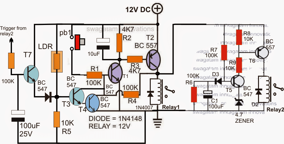
T1/T2 along with associated components form a latch circuit and gets triggered as soon as P1 is pressed.
The latching activates relay#1 which may be assumed to be wired with the motor and the ignition system. As proposed this starts the motor and the ignition sparking.
The adjoining stage comprising T5/T6 constitutes a delay ON timer which simultaneously begins counting once the above system is initiated.
C1/R7 decides the delay ON period which may be appropriately set for achieving the desired 5/6 seconds. once this delay period is lapsed relay2 is switched ON which may be assumed to be configured with a solenoid mechanism for spraying oil over the ignition chamber.
Once this is actuated, the flame lights up and illuminates an LDR which could be seen integrated with the Darlington T3/T4.
T3/T4 conducts in response to the illumination and instantly breaks the latch and the relay1 activation.
The motor and the sparking are inhibited from the supply and are instantly switched OFF.
The T7 protection stage ensures that in case no flame is sensed, after a couple of seconds it triggers and switches OFF the whole system.
The above explained automatic ignition burner mechanism could be also effectively used for vehicle button start implementation.
For a condition where the motor is required to keep running after the flame is detected, the above circuit may be modified as given under:
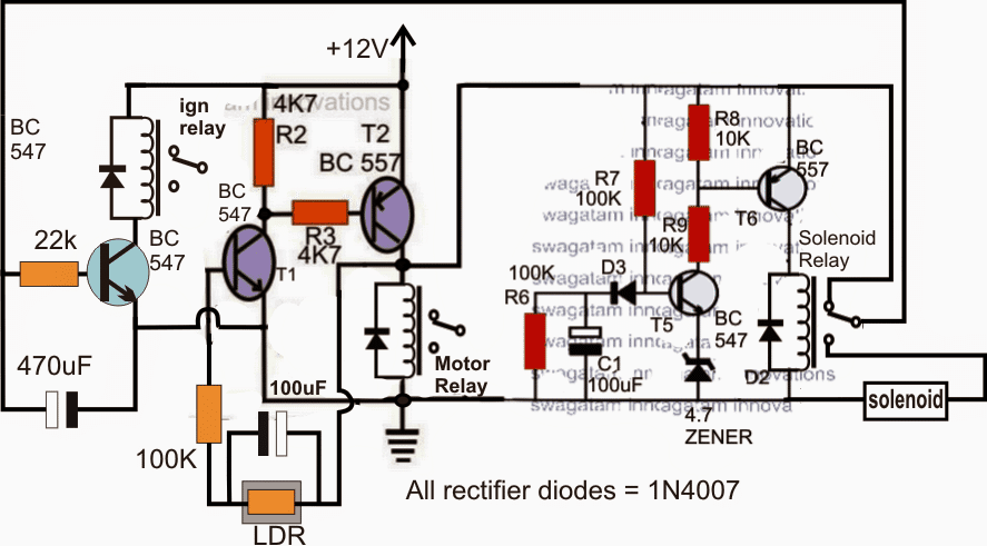
Here, when power is switched ON, T1/T2 get self-latched, the 100uF capacitor in parallel with the LDR ensures a feedback latch voltage for sustaining the latching effect.
The ignition relay also simultaneously gets switched ON through the N/C biasing voltage of the solenoid relay.
After 5/6 seconds when solenoid relay activates, the ignition still holds on due the presence of the 470uF capacitor.
The flame illumination overrides the 100uF capacitor and keeps the motor operative, however the ignition relay deactivates after a while when the 470uF is fully discharged.
In case the flame does not strike, the 100uF capacitor parallel to the LDR charges fully and breaks the latch switching OFF the motor relay, the solenoid relay as well as the ignition relay.

Comments
Sir I have seen your circuit it's quite interesting but I want know what is the correct value of relay and capacitor's…???? Please reply as soon as possible
Sandeep, relay can be a 12V/400 ohm type….which capacitor are you referring to?
Great but Im confused. I think chris said after the ldr sees a flame the ign is to shut down but the motor is to continue to run… how would this be corrected.also how could you add an adjustment for the sensitivity of the ldr and a way to shut it off that would still allow the motor to run a few min.(another timer I guess) to allow it to cool it down..
I'll check how it can be adjusted in the given circuit…
Good short, Swagatam!
But you forgot P1 in the schematic.
Sir please mention the correct value of relay and capacitor's please reply as soon as possible
Thank you Abu-Hafss,
I have corrected the diagram, please check it out
kind Swagatam, I have a boiler flame igniter control unit that goes into lockout because the flame detector does not work, which component could be broken in your opinion thank you very much. I could also send some photos
my email is palcanz@libero.it my best regards from Italy
Palmo Canzolino
Hi Palmo, I will need a schematic diagram of the system to understand its working and a possible solution, external pics will unfortunately not help