Along with social distancing and masks, the other major thing the post COVID-19 era has compelled the world to implement is to go touchless. This is being recommended for the many public devices, such as doors, hand sanitizers, buttons, switches etc. in order to restrict the spread of viruses that may be caused due to physical touching of buttons and handles.
The article makes an effort in supporting the touch-less or touch-free concept for doors, by upgrading the door system into electronic door system, which can respond to a human presence and perform the opening and closing operations exclusively without the need of manual pulling or pushing of the door.
Circuit Description
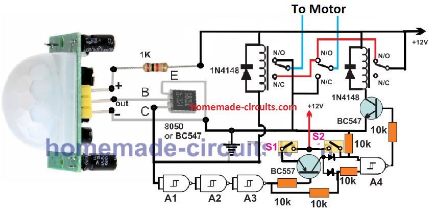
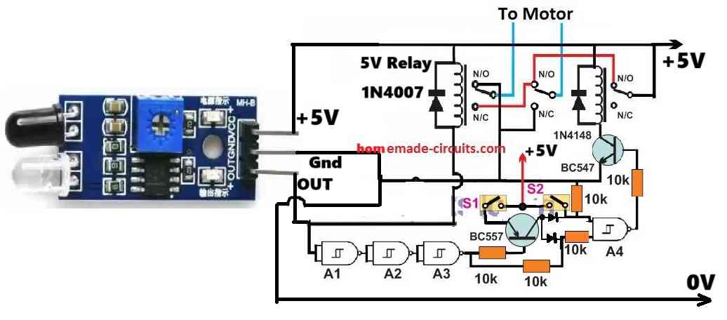
The touchless door circuit based on a PIR human detection is shown in the above figure.
Let' learn its working with the help of the following points:
The design works by using the following main components:
- PIR sensor
- DPDT/SPDT relays
- IC 4093
- Magnetic Reed Switches
PIR Assembly: The left side white dome shaped device, mounted on a green PCB is the Passive Infra Red or the PIR module. The module detects the infrared heatmap emanating from a human body and converts them into a positive potential at its output terminal.
As can be seen the module has 3 pinouts viz Vcc or the positive supply pin, the OUT which produce the output potential in response to a human presence within its detection range, and the Vss pinout which is the ground or the negative supply pin of the device.
In the above figure the 3 pinouts of the PIR is directly sldered with a current limiter 1k resistor and an amplifier transistor.
The 1k provides a quick and a reliable compatibility for the PIR with the 12 V supply, since it is fundamentally a 5 V device, and 12 V direct connection may cause a permanent damage of the device. The transistor works like an amplifier which converts the low current, low voltage output from the PIR to an adequately higher level for operating a relay.
The direct assembly of the mentioned parts on the pins of the PIR ensures a guaranteed and a reliable working of the PIR without the need of any special PCB or stabilizing elements.
Relay Working: The relay connected with the PIR transistor switches ON when the PIR detects a human, and switches OFF when a human moves away from its detection range. This relay is a DPDT type which has two sets of N/O, and N/C contacts.
These contacts are wired with a power motor to enable a forward and backward rotation in response to the activation and deactivation of the DPDT relay.
There's also a second another relay which is an SPDT type, meaning with a single set of N/O, N/C contacts. This relay provides the positive supply to the DPDT relay contacts and the motor, such that this supply is cut OFF whenever the motor pulls the door at the either ends of the open/close limits.
NAND Gates: The circuit uses 4 NAND gates from the IC 4093, which control the SPDT relay for the required deactivation of the motor as soon as the door is rolled at the extreme ends of it travel.
Reed Relay: Two reed relay switches are used in this automatic touchless PIR door controller circuit. The reed switches provide the necessary electrical signals to the NAND gates to ensure that the motor is shut off when the door is pulled across their either limits.
Circuit Working in Details
The polarity of the motor wires are connected with the DPDT relay in such a way that the N/C or normally closed contacts enable the closing of the door, and the N/O or the normally open contacts enable the opening of the door.
Let's assume that the touchless door is in a completely closed position, and no human-being present within the detection range of the PIR.
In this position the DPDT relay is in the deactivated state with its contacts resting across their N/C points.
Also, the reed switch S1 is suitably positioned externally such that when the door closes it aligns with a magnet installed at the edge of the door.
Similarly, S2 reed switch is positioned to respond with another magnet associated with the door, when the door is in the open position.
Thus, S1 now being in close proximity with the door magnet, is in the closed and conducting condition.
Also, since the PIR is witched OFF, the 8050 transistor is also switched OFF, causing the input of gate A1 to be high.
Since the NAND gates are wired as inverters, the output of A3 in this situation turns low or 0 V.
This 0 V causes the BC557 to switch ON, and apply a positive supply via S1 to the two inputs of the gate A4.
A4 gate as a result turns low, or 0 V keeping the the BC547 and the associated relay switch OFF. This cuts off the supply to the DPDT relay and the door motor stays deactivated.
The whole system now waits in a standby position.
Now, suppose a human approaches the door, and comes within the PIR range. The PIR switches ON, activating the DPT relay in the N/O position.
The PIR activation also causes a low signal to appear at the input of gate A1, which in turn causes the output of A3 to go high.
This action switches OFF the BC557, causing the input of A4 to get 0 and 1 logic at its inputs, which turns it output high and activates the BC547 and the associated SPDT relay.
The SPDT now provides the required supply to the DPDT and the motor.
The motor quickly activates and begins rolling the door in the open position.
Once the door is fully open, S2 reed activates, causing a logic 1 to appear at the respective input of A4. The other input being already high or 1, the output of A4 turns low, causing the BC547 and the SPDT to switch OFF.
The supply is immediately cut off and the motor halts.
The person is now enters the door and moves ahead out of the range of the PIR.
The PIR now switches OFF, switching the DPDT towards the N/C contacts which is supposed to reverse the motor operation. This also causes a high at the input A1, and a low at the output of A3. This results to the inputs of A4 to get 0 and 0 logic respectively, turning its output high, and switching ON BC547 and the SPDT relay.
The SPDT initiates the supply to the DPDT and the motor so that the motor now begins pulling the door towards the closed position.
Here, the S2 opens causing a low at the respective input of A4, but that does not affect the A4, since a 0 and 1 still keeps the A4 output high.
Finally, when the door reaches closed position, the reed relay S1 conducts, and the entire system comes to a halt and in a standby condition.
Automatic Sliding Touchless Gate Operation
The above explanation touchless door concept could be also effectively applied for implementing an automatic touchfree sliding gate system.
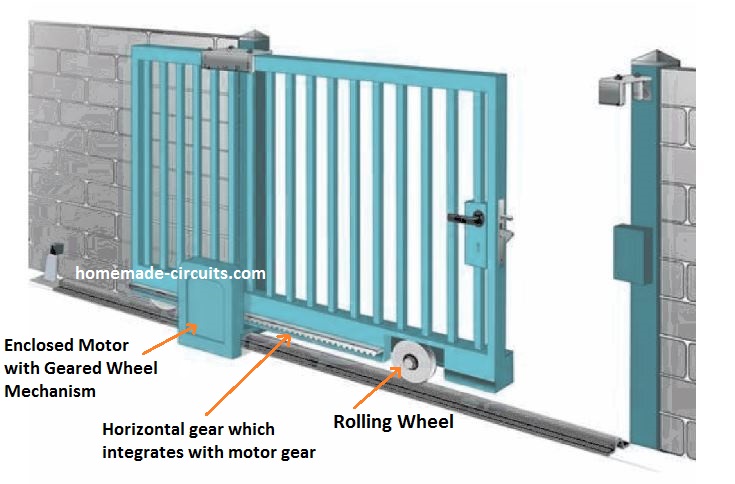
The mechanism for the gate system can be visualized in the above figure.
The gate is slides with the help of a couple of wheels.
One wheel is fitted at the front end of the gate which supports the gate to roll freely across the metal rail track.
The other wheel which is in a gear form is fitted on the motor shaft such that its teeth couples with the teeth of the horizontal gear installed at the bottom of the gate.
Now, as the motor operates, the gear wheel bites the horizontal gear teeth and forces the gate assembly to roll towards the direction as determined by the clockwise or anticlockwise movement of the motor gear wheel.
Upgrading a Standard Door into a Touchless Door
For converting an ordinary or a standard door system into a touchless version, the following simple motor pull-push mechanism could be employed.
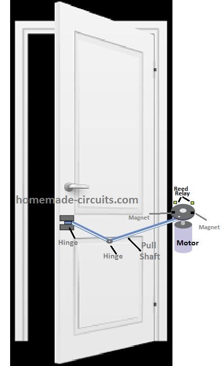
Here, we can see a shaft is joined in the middle and the ends through separate hinges, which allows the shaft to be flexible and bend at the required angles for enabling the pulling or pushing of the door in response to the rotation of the motor disc.
The magnets and reed relays are fitted across the motor disc, such that the respective magnets and the reed switches align with each other during the opening and closing of the door at the predetermined angles.

Questions & Answers
please can you give me a circuit that uses Ultrasonic sensor module instead if PIR. Without Arduino or any other microcontroller
If an ultrasonic proximity sensor module is used then Arduino will be required, because this module cannot work with analog circuits…
can you tell about all componts and devices that use in the circuit like A1,A2,A3,A4,8052
A1—-A4 ae the gates from the IC 4093, 8050 is a transistor
I don’t have very much experience wiring relays from a schematic, and I am having trouble with a circuit I am trying to build, which calls for a SPDT and a DPDT. Would someone be able to draw out on a picture or write out as text specifically where the pins go exactly on the relays themselves, I can’t seem to get it right?
You can purchase a transparent DPDT relay and check the details visually. The terminals with are connected to the coil of the relay are the coil terminals. The center two spring loaded shafts are the common terminals. These common terminals could be seen touching two other contacts due to spring tension, and these two contacts are the N/C contacts, while the remaining two contacts which are open and which will connect with the spring loaded shafts when the coil is powered are the N/O contacts.
You can learn correctly only when you practically test the relays.
Hello Swagatam, thank you for the circuit.
please can you give me a circuit that uses IR module instead if PIR.
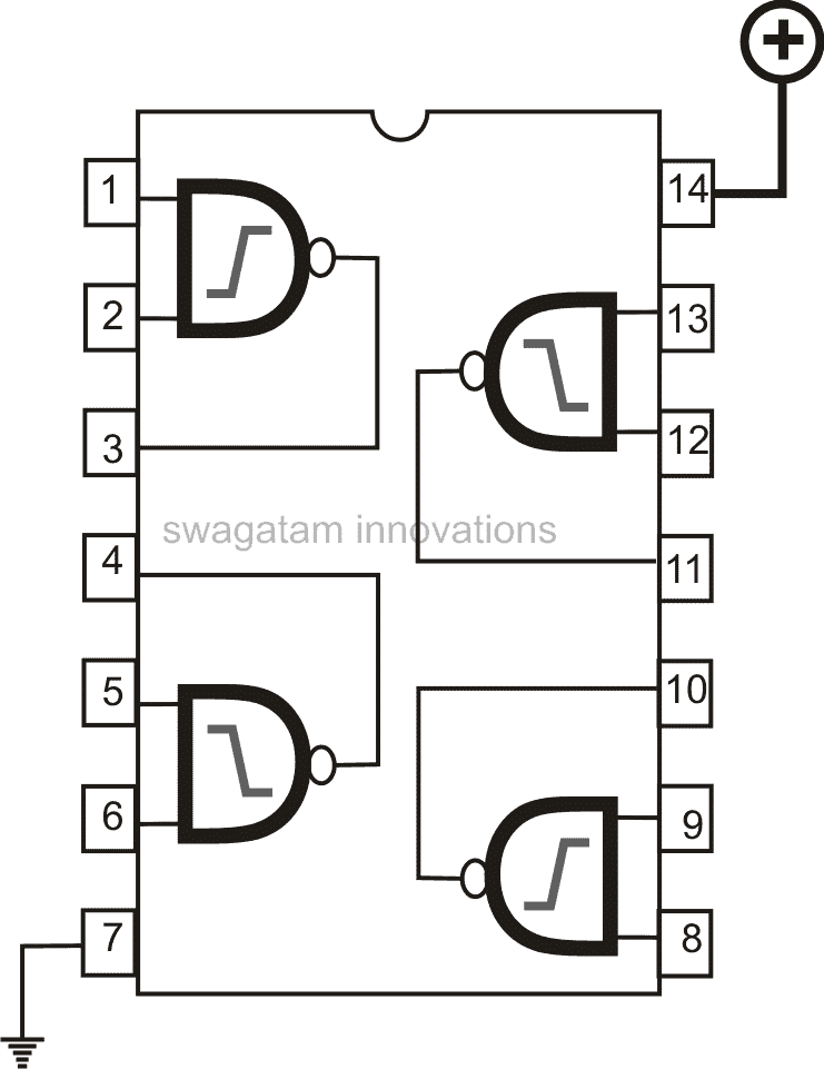
also I don’t understand how to wire the gates in ic4093 which i think are pins 1,5,8 and 12 of the ic.
Thank you Alfred,
You can try the following design for controlling the door using ordinary IR LED module:
You can use the following 4093 diagram for configuring the pinouts:
thank you so much. I appreciate it.
You are welcome…
I am a subscriber and enjoy pondering each project you put forth, thanks. I have an old electric Golf Cart which uses the Resistive Coils to control the four speeds via the Drive Motor, using copper contacts, wiped by mechanical linkage from the accelerator pedal. I am wondering if I could get rid of all that heat, from the coils, and use, instead, Power Mosfets to vary the Duty Cycle Pulses to the drive motor for each of the four speeds? Scanning thru your huge bank of circuits I don’t see a similar one (probably overlooked it) using power mosfets controlling a DC motor. Thanks for you consideration.
Thanks Ron, I appreciate your feedback.
You can try the following links which explains a few effective pwm mosfet controlled motor circuits
2 Simple Bidirectional Motor Controller Circuits Explored
3 Simple DC Motor Speed Controller Circuits Explained
Very nice topic. I was looking to know about this system. Very clear and very instructive. Thanks a lot.
Glad you found the post helpful, and thanks for stopping by!