A simple tea, coffee vending machine circuit idea is explained here which allows a customer to access the beverage with a press of a button and by inserting a genuine 5 rupee coin. The idea was requested by Mr. Ramesh.
Circuit Objective and Requirement
I need the water puling mechanism like coffee vending machine if we need 100 ml of water it should be pull 100 ml water or if we need 200ml it should be pull 200ml water please help me on this.
The Design
As per the request above, a simple beverage pulling machine could be built by using the following circuit:
Referring to the diagram, it's a simple monostable timer made around the indispensable evergreen IC 555.
Pressing the yellow/blue button triggers the IC in the counting mode and simultaneously actuates the relay.
The relay switches ON the 12V liquid controller solenoid valve which opens internally and allows the beverage to pass through it until the counting period is elapsed, and the IC switches OFF the relay.
Circuit Diagram
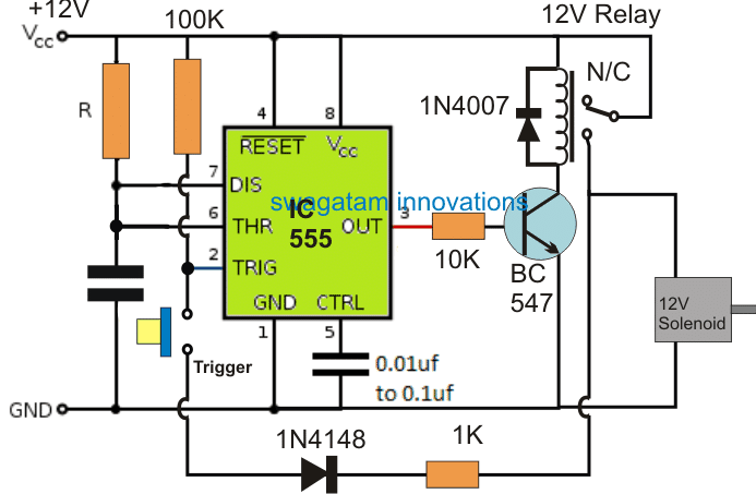
The desired delay period for which the relay and the solenoid should remain switched ON can be calculated using this IC 555 calculator software.
The above design only takes care of the timed solenoid operation in response to pressing of a button, however for implementing the design accurately as a tea/coffee vending machine circuit, it needs to be upgraded with a foolproof payment option, so that the customer is able to insert a legitimate 5 rupee coin for accessing the beverage.
Making a Tea Coffee Vending Machine
In order to upgrade the above concept into a tea or coffee vending machine, the unit must preferably include a foolproof payment accepting facility.
I have tried to implement this by introducing a system which will hopefully be able to detect the difference between a genuine 5 rupee coin and a false one.
Although recognizing and confirming a currency coin through ordinary means is impossible, the following technique offers some degree of accuracy and makes sure no duplicate metal coin can be used for accessing the beverage.
Coin Weight Detection
I have tried employing a weight detection, and a non-ferrous (non magnetic material) detection procedures for the coin, the design can be learned from the following explanations:
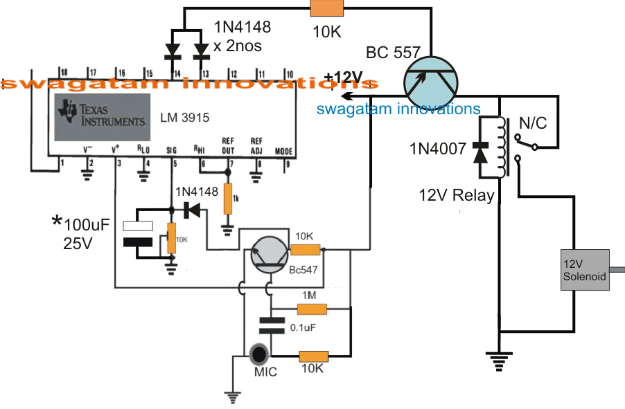
The above circuit can be used for roughly determining the weight of the coin by allowing the coin to strike on an electret mic and then measuring the striking or vibrational force through a LM3915 circuit.
Heavier coin will supposedly create higher voltage spikes from the MIC output, and vice versa.
The difference in the intensity of the voltage spikes will hopefully create corresponding levels of voltage shifts across the output pins of the IC from pin#1 to pin#10.
The 10k preset at pin#5 is appropriately adjusted such that a genuine coin generates a spike that may reach around pin#13/14. This level would be held intact for so long as the 100uF capacitor is discharged.
Since the relay driver transistor BC557 is attached with the pin#13/14 of the IC, it should immediately conduct whenever a legitimate coin is inserted, and subsequently actuate the relay and the solenoid.
The solenoid actuation allows the person to collect the beverage in the form of tea or coffee in the cup.
In case a false imitation coin is inserted which may be lighter or heavier in mass might create a voltage spike either not sufficient to go up to pin13/14, and might only reach across the lower pinouts of the IC, or surpass the pn13/14 of the IC and trigger the upper irrelevant pinouts of the IC.
In either case the relay driver transistor would not activate thwarting the false attempt by the fake coin
The 100uF capacitor is arbitrarily selected, this needs to be tweaked with some trial and error to ensure that the relay activates for a period of time that may be just enough for filling the beverage cup up to its rim.
Non-Ferrous coin Material detection.
A true 5 rupee coin is supposed to be non-ferrous and non-magnetic.
The coin could be tested for its non-ferrous condition by the following method:
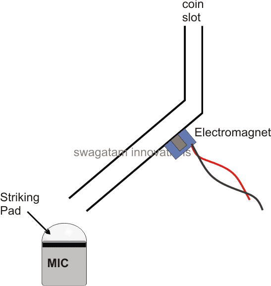
In the above set up we can see how the proposed MIC needs to be arranged along with a channelized guide for enabling the coin to slide down to the destination from its drop slot.
The channel or the pipe through which coin must pass can be seen connected with a strong electromagnet from the outer side of the tube.
This electromagnet needs to be continuously switched ON throughout the operational period of the machine, so that in case a fake coin (made up of iron or steel) is inserted, it gets caught with the electromagnet and the beverage is never made available to the person attempting the theft.
If you have any doubts or questions regarding the above explained tea, coffee vending machine circuit, you may feel fee to ask the same through the comments.

Questions & Answers
Hello sir! I want to make a coffee, tea and juice vending machine using digital logic, as my college project. Can you please provide a circuit for this project ASAP. It would be a great help.
Hello Lisa, I am sorry I do not have a digital wending machine circuit with me at this moment.
Hi Sir, I am Naresh from chennai. I would like to startup a tea shop and i start search about vending machine in that time i saw your home circuit projects for vending machine. Can i able to make a vending maching using this circuit or its only for study purpose. Could you able to advice regarding this.
Hi Naresh, the first circuit being a simple design can be made without much worries, but the second circuit has many operations and can be built only by an expert who knows exactly how the various stages are working and how to troubleshoot them in case of a fault. So if you are an expert in electronics then you can try the second circuit, otherwise the first is the recommended one for you!
Hello sir, i want to do it as a college project. I didn’t understand why LM3915 is used here. Can you please explain me it’s function. And what mic can we use here to measure weight of the coin?
Hi Sai, depending on the voltage level on pin#5 of the IC, its output produces a shifting low signal sequentially through pin#1 to pin#18, 17…10
If the voltage spike is on the lower side, the output sequence wil be restricted on the lower half of the pinout order, for higher spike the low signal may reach upto the higher range of the pinout. When the 10k preset is correctly adjusted as per the 5 Re coin’s striking force, the sequence may reach upto pin13/14 and switch ON the solenoid for dispensing tea…you can use an electret mic or simply a 27 mm piezo directly connected across the pin5 and ground.
Please note that this concept is based on my assumption only, and therefore may require a lot of tweaking until the desired results can be achieved.
hello sir can u please explain why are we connecting the diode 1n4148 only to pin number 13/14.
Without the diodes the pins of the ICs will get shorted.
Hello. i hope u are good. can u please explain how you 555 timer circuit works.
It works like a one shot timer or a monostable. On pressing the button, the pin2 finds a ground path via the motor, which triggers the IC into counting mode.
Can I ask the complete circuit diagram for this?? I badly need this for my school project 🙂 thanks a lot!
if it's for a school project then I think the first idea should be enough…the second diagram can be too complex for you…
the details of the first diagram is already furnished in the diagram itself.
hi SWAGATAM that is so great now i dont need any person to monitor tea level in the huge container cant you add a circuit which refills tea every time it reaches a low level . and how is it maintained or done every time a customer finds hot tea
Thanks Davis, It could be done using an LDR/Laser circuit, if possible I'll try to update it soon…
Nice idea.
Have you made an implementation of this or do you know anyone who has done this project without arduino?
I need it for reference sir
The first one is tested, the second circuit is not tested.