In this article I have explained a couple of circuits that will allow automatic watering of plants and flower pots, even while the owner of the house is away from home, and the house is locked for many days.
The first method is through a sound activated system which detects the sound from a cellphone ringtone and activates the water pump, the second method is through a programmable timer, which activates the pump for a preset amount of time, each day.
Let's begin by understanding the first concept using a cellphone and a sound activated switch circuit
Cellphone Controlled Plant Watering
The idea was requested by one of the ardent readers of this blog, Mr. Akhilesh. The following paragraph explains the requirement of the design:
I want to make a circuit which either auto switch on the water pump just for 2 min or activates with sound and off after 2 min.
Actually, when my family goes out of station for a week, All plants die due to lack of water. So I am planning to make a circuit that can control a small motor (Water cooler pump) and every day automatically switch on at specific time and off after 2 min. or a circuit that can work with sound activation, for example I put a mobile phone near circuit and when I call on that phone, motor switches on and off for 2 or 5 min.
In this cellphone controlled plant watering circuit we use a sound activated switch circuit, and place a low cost mobile phone near the MIC of the circuit.
The sound activated circuit has a relay, which is connected to a water pump unit, which supplies water to the plants.
The relay remains activated as long as some sort of audible sound remains close to the MIC of the circuit. In this design, a cellphone ringtone is used to make the noise near the MIC, which triggers ON the circuit.
The owner has to simply call the cellphone number which is placed near the MIC of the sound activated circuit.
As long as the ringtone remains switched ON near the MIC, the relay remains activated, keeping the water pump switched ON, and this allows water to be supplied to the plants or the flower pot.
When the ringtone ends, the water pump stops pouring water to the plant.
Thus, the owner of the house has full control of the situation, which allows him to supply water remotely to his home plants whenever it is required.
The following figure shows the entire set for the mobile controlled plant watering circuit.
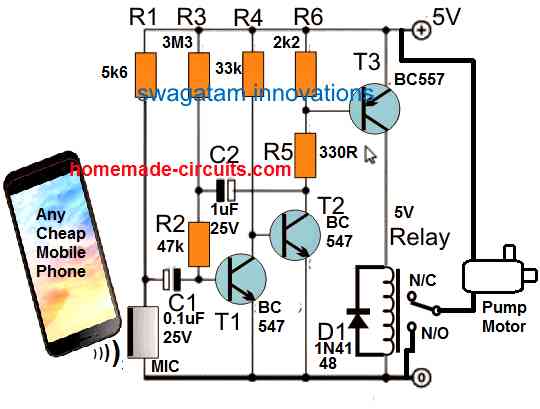
The working of the circuit can be understood with the following points:
When the cellphone which is shown near the MIC is called by the owner, its ringtone noise is detected by the MIC. This triggers the transistor T1, T2, and T3 in succession, which finally turns ON the relay.
The relay can be seen attached with a tiny 6 V water pump, which s switched ON. It remains switched ON as long the ringtone remains active from the cellphone.
The transistorized circuit is basically a MIC amplifier circuit, which amplifies the small electrical signals from the MIC, generated due to the ringtone sound.
T1 does the job of a preamplifier, while T2 and T3 further amplifies the preamplified signal from T1, so that the current becomes sufficiently large to switch ON a relay.
The capacitor C2 determines for how long the relay can continue to remain ON after the ringtone has stopped.
R1 decides the sensitivity of the circuit to sound inputs. If you want to ensure the MIC circuit does not get triggered due to stray external sounds, you can increase the value of R1 to 10 k or higher.
The cellphone controlled plant watering circuit is simple and cheap, but it has one drawback, it cannot send an SMS back to the owner to confirm regarding the actions, which means the owner can never know whether the water pump was actually activated or not. Nevertheless, the transistorized circuit being small and simple is extremely reliable and it will respond impeccably to the ringtone sounds and activate the water pump relay without fail.
Timer Based Automatic Plant Watering Circuit
A timer based automatic plant watering circuit ensures that the water pump switches ON for a specific amount of time everyday at a predetermined time.
The proposed circuit is actually a long duration timer, with a transistorized monostable output, as shown the following diagram.
The timer IC 4060 is configured in a simple oscillator mode.
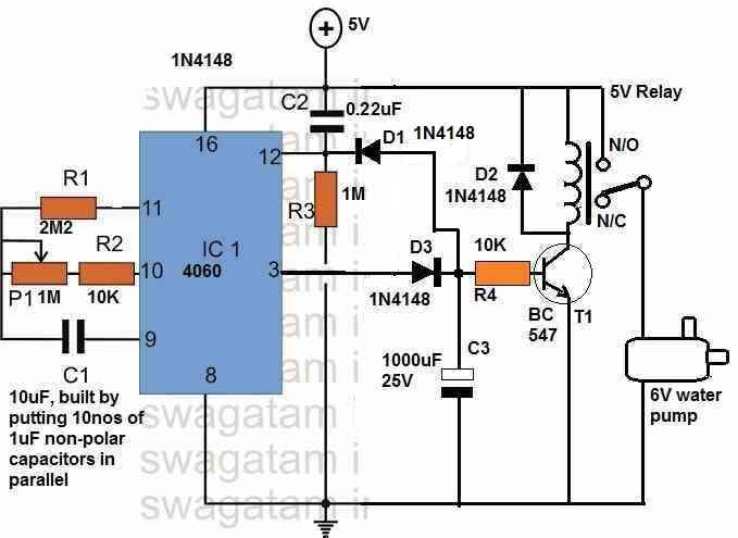
The delay period of the oscillator is determined by the components P1, R2, and C1. The delay determines for how long the relay remains switched OFF and at what time of the day (or night) it switches ON the water pump.
You will find that the IC has many pinouts which generate the output oscillations at different frequency rates, each being twice of the previous output pin.
Out of all the output pins, the pin#3 generates the lowest frequency, or the highest delay, or the highest ON time period outputs.
For this reason pin#3 is selected for generating the time intervals for the relay and the water pump activation.
When power is switched ON, the C2 momentarily resets the IC by supplying a short high pulse on its pin#12.
The resetting ensures that the IC timing begins from zero, with pin#3 initiating with a low output.
While the IC counts, the pin#3 remains low, which allows the transistor-relay stage to remain switched OFF.
As soon as the IC timing elapses, the pin#3 turns high and a couple of things things happen simultaneously.
The high signal enters D3 charging up C3, and it also passes through D1 to hit pin#12, which resets the IC, so that pin#3 turn instantly turns low again, and the counting begins afresh. This process is crucial as it ensures that the delay cycles are almost identical in length, without discrepancies.
However, this short momentary pulse is enough to charge C3 fully and cause the transistor T1 to switch ON.
When T1 switches ON, the relay also switches ON, which turns ON the water pump.
The charge inside C3 ensures that T1 remains remains ON for sometime, maybe for 5 to 8 seconds, which is enough time to water a flower pot or any small plant.
If you want the relay to be switched ON for higher amount of time, you can replace T1 with a Darlington transistor, and increase the R4 value to 100K, which may increase the relay ON time to around a minute.
Wow, nice job here.
Can it possible to get the prototype of this from u?
sorry prototype may not be possible.