• Skip to main content
  • Skip to primary sidebar

Homemade Circuit Projects

Need circuit help? Post them in the comments! I've answered over 50,000!

Blog | Categories | About | Contact | Calculators-online
You are here: Home / Water Controller / Capacitive Fluid Meter Circuit for Sealed Tanks

Capacitive Fluid Meter Circuit for Sealed Tanks

Last Updated on April 11, 2021 by Swagatam 5 Comments

At times it becomes important to determine the amount of water inside a sealed tank, by employing a stationery sensor. A sensible remedy to the issue is to make use of a cylindrical capacitor concept. One plate of the capacitor is created with the liquid surrounding an insulated conductor, where insulation of the conductor works like the dielectric while the capacitor's second plate is formed by the wire itself.

Table of Contents
  • Basic Idea
  • How it Works

The capacitive fluid meter presented in the following article allows the user to know or see the fluid level inside a sealed tank through a meter reading, using an insulated copper wire fixed inside the tank which acts like a capacitive sensor.

Basic Idea

The idea is actually simple but interesting. An insulated wire is dipped inside the tank fluid, the fluid is applied with a ground or negative potential, while the internal conductor of the insulated wire is connected with an external detector/amplifier circuit.

The conductor inside the insulation is unable to come in direct contact with the fluid, however, it is able to detect the fluid through capacitive effect, with respect to the ground connection of the fluid.

When the fluid level is high, the capacitive effect is higher around the insulated conductor, and vice versa. This capacitive influence is detected by the external circuit and an equivalent reading is translated over a moving coil meter.

The liquid level inside the sealed tank will be proportionate to the capacitance of this liquid/conductor electrode, which could be determined by a straightforward circuit for converting the linearly varying nature of this capacitor into a linearly varying voltage level, which may be proportionate to its capacitance.

How it Works

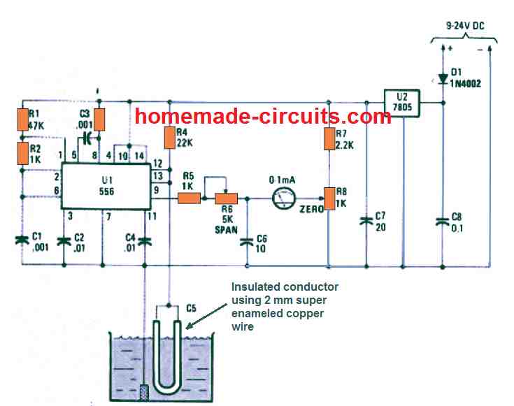
The center of the capacitive fluid meter circuit as shown in the diagram, is a monostable circuit configured with the help of the capacitive transducer inside the fluid and 1/2 of a 556 dual oscillator/timer.

warning message: electricity is dangerous, proceed with caution
capacitive fluid meter circuit compressed

The PWM output from the monostable is relative to the capacitance of the RC timing circuit consisting of R4 and the adjustable capacitance of the fluid/conductor capacitance C5, which is directly proportional to the total area of the conductor dipped inside the liquid.

The other 1/2 of the IC 556 timer is configured like a clock operating at 22 kHz that delivers the trigger pulses to the monostable. Depending on the level of the fluid inside the tank, the capacitance of the "C5" probe varies, which in turn causes the monostable timing to vary.

The varying monostable output from IC is fed to a moving coil ammeter which converts the varying pulses into a meter reading that directly proportional to the the fluid level inside the tank.

A graphite rod removed from your old lantern battery can also used as the ground probe in a situation when the tank is made up of a non-conductive material. Potentiometer R6, a 5K unit, can be used for calibration of the meter's range.

You'll also like:

  • 1.  Pressure Switch Water Pump Controller Circuit
  • 2.  Simple Automatic Plant Watering Circuit for Monitoring Soil Moisture
  • 3.  Two Pipe Water Pump Valve Controller Circuit
  • 4.  Solar Drip Irrigation Circuit for Indoor Gardens
  • 5.  Digital Clock Activated Water Level Controller Circuit
  • 6.  Safety Buoy Switch Circuit for Human Powered Submarine

About Swagatam

I am an electronics engineer with over 15 years of hands-on experience. I am passionate about inventing, designing electronic circuits and PCBs, and helping hobbyists bring their projects to life. That is why I founded homemade-circuits.com, a website where I share innovative circuit ideas and tutorials. Have a circuit related question? Leave a comment.... I guarantee a reply!

Previous Post: « 7 Easy Sawtooth Waveform Generator Circuits using UJT, IC 555, and Transistors
Next Post: Automobile Tester Probe Circuit [Car Fault Finder Probe Circuit] »

Reader Interactions

Comments

  1. Kim says

    April 12, 2021 at 10:23 am

    What would be the issues if this circuit was used in a black water holding tank?
    Would the dried affluent effect the capacitance on the probe and/or the graphite ground probe?
    Probes for measuring tanks with affluent have historically failed due to clogging, corrosion, and layers of impurities drying on the probes.

    Reply
    • Swagatam says

      April 12, 2021 at 5:09 pm

      It should work, since the affluent would be full of minerals, which will help greater conduction and capacitive effect. The central sensor wire is supposed to be a super enameled insulated copper wire so corrosion can never happen in this concept.

      Reply
  2. Mitch Tyson says

    April 11, 2021 at 6:51 am

    An arc will not ignite a flammable fluid if it occurs in the liquid. If the arc occurs above the liquid surface, it still will not ignite. It is only when the vapors of the liquid combine with air at the proper ratio that combustion occurs.

    Reply
  3. Bush says

    April 9, 2021 at 7:23 pm

    Will this circuit work for Petrol? E.g, as a motorcycle fuel Gauge?

    Reply
    • Swagatam says

      April 9, 2021 at 8:54 pm

      If the ground link is held close to the copper wire then perhaps it might work with petrol or gasoline tanks also…

      Reply

Need Help? Please Leave a Comment! We value your input—Kindly keep it relevant to the above topic! Cancel reply

Your email address will not be published. Required fields are marked *

Primary Sidebar

Subscribe to New Circuit Ideas

Categories

  • Arduino Projects (87)
  • Audio and Amplifier Projects (132)
  • Automation Projects (17)
  • Automobile Electronics (101)
  • Battery Charger Circuits (83)
  • Datasheets and Components (104)
  • Electronics Theory (143)
  • Free Energy (37)
  • Games and Sports Projects (11)
  • Grid and 3-Phase (19)
  • Health related Projects (25)
  • Home Electrical Circuits (12)
  • Indicator Circuits (14)
  • Inverter Circuits (87)
  • Lamps and Lights (142)
  • Meters and Testers (69)
  • Mini Projects (46)
  • Motor Controller (64)
  • Oscillator Circuits (27)
  • Pets and Pests (15)
  • Power Supply Circuits (108)
  • Remote Control Circuits (50)
  • Security and Alarm (64)
  • Sensors and Detectors (101)
  • Solar Controller Circuits (59)
  • Temperature Controllers (42)
  • Timer and Delay Relay (49)
  • Transmitter Circuits (29)
  • Voltage Control and Protection (37)
  • Water Controller (36)

Calculators

  • Battery Back up Time Calculator
  • Capacitance Reactance Calculator
  • IC 555 Astable Calculator
  • IC 555 Monostable Calculator
  • Inductance Calculator
  • LC Resonance Calculator
  • LM317, LM338, LM396 Calculator
  • Ohm’s Law Calculator
  • Phase Angle Phase Shift Calculator
  • Power Factor (PF) Calculator
  • Reactance Calculator
  • Transistor Astable Calculator
  • Transistor base Resistor Calculator
  • Voltage Divider Calculator
  • Wire Current Calculator
  • Zener Diode Calculator
  • Filter Capacitor Calculator
  • Buck Converter Calculator
  • Boost Converter Calculator
  • Solar Panel, Inverter, Battery Calculator
  • Wire Current Calculator
  • SMPS Transformer Calculator
  • IC SG3525, SG3524 Calculator
  • Inverter LC Filter Calculator

People Also Search

555 Circuits | 741 Circuits | LM324 Circuits | LM338 Circuits | 4017 Circuits | Ultrasonic Projects | SMPS Projects | Christmas Projects | MOSFETs | Radio Circuits | Laser Circuits | PIR Projects |

Recent Comments

  • Swagatam on 10 LED Tachometer Circuit Diagram
  • Swagatam on How Shunt Regulator TL431 Works, Datasheet, Application
  • Göran on 10 LED Tachometer Circuit Diagram
  • SA on How Shunt Regulator TL431 Works, Datasheet, Application
  • Swagatam on Adjustable 0-100V 50 Amp SMPS Circuit

Company

  • Privacy Policy
  • Cookie Policy
  • About Me
  • Contact
  • Disclaimer
  • Copyright
  • Videos
  • Sitemap

Social Profiles

  • Twitter
  • YouTube
  • Instagram
  • Pinterest
  • My Facebook-Page
  • Quora
  • Stack Exchange
  • Linkedin
  • © 2025 · Swagatam Innovations