In this post we study a simple rechargeable LED lantern circuit which features battery charging option from a dynamo as well as from a mains 220V source. The idea was requested by Mr. Chidimonday.
Technical Specifications
I like what you doing here, i have even put in work some of your circuit and it functioned well, please sir can you help me, am writing from Nigeria, please i need a circuit diagram of 9v rechargeable lantern using dynamo and also electric current, thanks,i will be grateful if you respond back immediately, you can, send it through my Gmail account (chidimonday@gmail.com)
The Design
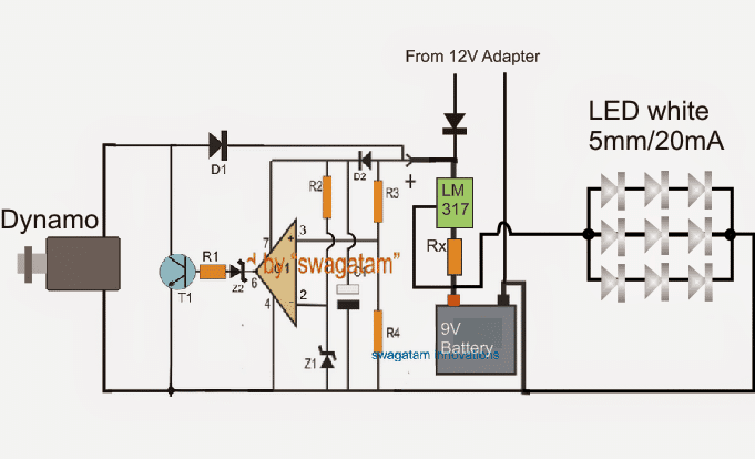
The simple diagram presented above explains how a 9V battery may be charged from a dynamo and also from an external 12V DC source simultaneously or separately, and subsequently used for powering an LED lantern.
The opamp IC along with the shown associated component basically forms a shunt regulator stage, which regulates the dynamo voltage and current by shorting its power to ground whenever it tries to exceed the 12V mark.
The controlled 12V is allowed to pass to the connected 9V battery for charging via a LM317 current limiter stage.
The DC acquired from an external source such as from an AC/DC wall adapter can be also seen fed at the input of the LM317 regulator, which is further appropriately trimmed down by the LM317 stage in order to enable a safe charging for the connected battery,
The value of Rx can be calculated as per the information provided in the following article:
Universal current limiter circuit for high watt LEDs
Parts list for the proposed LED lantern circuit using a dynamo and mains AC
R1, R2, R3 = 10k
R4 = 6.4K
Z1, Z2 = 4.7V zener diode
T1 = TIP122
IC1 = 741
D1, D2, D3 = 1N4007
C1 = 100uF/25V


Questions & Answers
I want to use 20 leds what value will be of Rx. I don’t want to use dynamo what other can I use here. Please kindly guide me. Thank you.
If the battery is 9V then the LED series must in multiples of three ( 3 x 6). So you can use 18 LEDs.
Assuming the LEDs are 20 mA rated
Out = Vref / RX
RX = Vref / out
= 1.25 / 1.2 = 1.04 Ohms or 1 ohms
power = 1.25 x 1.2 = 1.5 watts or 2 watts
Thank you so much for guiding me.
You are welcome!!
Hello sir,
I want to apply this circuit for charging an 18560 battery, and also an external charging source of 5V, please how do I go about this, thanks.
sorry correction: use a zener having a value equal to the 18560 charging voltage value….for example if it's 4.2V then use a 4.2V zener
Hello thomas, you can do that by using the same circuit which is explained above….replace the zener at pin#2 of the IC with a 5.1V zener, and remove R4…that's all
Sir i have some questions.
How does the dynamo functions in in the above circuti?
how is that can be triggered? it will need an external force in order the dynamo rotates and operates? what is the output voltage of the dynamo you used in your design?
can i used a 6v dc dynamo?
Thanks sir.
Angelous, It can be operated as per the user's convenience, it can be done through bicycle, through windmill set up or any similar mechanism which will enable the rotation of the dynamo
output voltage will depend on the dynamo specs…can be anything between 3 and 24V
6V will do..
Sir, the dynamo creates an electricity in the circuit above? then use it to charge the the battery?
yes that's correct
Sir me and my friend doing a project based on getting a electricity while driving the bike.we selected the 12v,1.3a rated pmDC motor from the DC fan.we used a exhaust fan turbine to rotate the shaft.while we driving a bike we get a rated voltage 12v and more with the speed of 40km per hour.now I need a circuit that the load should be connected only the voltage from a generator is above 12v
Thanks for your reply sir
Vijay, you can use the second circuit from the following article:
https://www.homemade-circuits.com/2012/07/make-6v-4ah-automatic-battery-charger.html
just interchange the pin2 and pin3 with one another, and adjust the pin3 preset such that the red LED just illuminates at arounsd12.2V
you'll need to remove the 100k resistor completely, and replace the 317 stage with the bike supply input
Sir.I have a doubt. If the dynamo generated voltage exceeds 12v it stops the battery charging or if the dynamo voltage exceeds 12v it will start the charging. I have a confusion in this area
Vijay, battery will stop getting the charging voltage whenever dynamo voltage tries to exceed 12V…..so it'll be like ON/OFF/ON/OFF/ON…..continuously making sure that the dynamo voltage is shunted each time it crosses the limit..