An automatic clock time triggered water level controller circuit which responds to a real time clock input is discussed in the following article. The design also includes a water detection stage which makes sure the initialization takes place only in the presence of water in the tank or the pipe. The idea was requested by Miss Soumya Mathur.
Technical Points
I make my each & every project form your guidance. i passed by 3rd yr only because of your project. Your r biggest help of mine. without you and your ideas....m nothing. You teach your each n every project in simplest possible manner.
Each and every student on my batch and even our seniors take help from your ideas and site. You can imagine how popular you are in our college, that college has blocked your site in our hostel premises LAN & wifi. That's why i access your site from my cell n writing u mail on gmail. I'm in final year and i need your help in my project.
If u don't help, i may FAIL in my project. Your Semi Automatic Water Level Controller/Timer Circuit (https://www.homemade-circuits.com/2012/04/cheap-semi-automatic-tank-water-over.html) is already made by one of our seniors. I am planning to modify it a bit.
I am planning for something different which is as follows :
1. on/off timer : it should have on/off timer. it can be real time (i.e. like alarm in cell) or simply fixed time (i.e. like on timer in tv).
similarly off timer also. if possible it should give me facility to off my ckt after every 15min till 120 min after ckt is on.
2. water checking : suppose timer is set to 6:00am, den at 6:00am before ckt gets switch on, it should check whether water is available in tap or in tank.
if yes, then only it should switch on ckt, else not. similarly if ckt is set on for 60min (6:00am) n water goes off after 45min (6:45am), then immediately ckt should cut-off n should switch off pump.
3. i want to run my home pump. i don't understand electrical much but its name plate is written 1.5kw 210V 15Amp.
PLEASE HELP SIR, IF U DON'T HELP I WILL FAIL BCOZ I HAVE ALREADY TOLD MY FACULTY DAT I M MAKING THIS PROJECT WID AL DIS ARRANGEMENT.
Thanks a lot sir in advance
Soumya Mathur
The Design
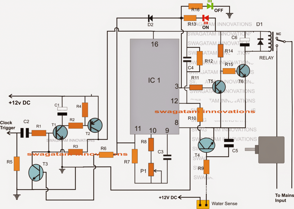
The circuit design of the proposed digital clock controlled, real time, automatic water controller circuit may be understood with the help of the following points:
Referring to the diagram above, when a clock positive pulse is received at the input of C2, the circuit consisting of T1 and T2 is latched, allowing the positive 12V to reach the IC1 stage.
The above action powers up the IC1 stage which immediately gears up into a counting mode with an initial zero logic at its pin3.
However the IC1 is able to initiate only in the presence of water in the tank or in the pipe which is detected by T4 through its base sensing plate.
If the presence of water is detected, pin12 of the IC is enabled with a ground signal so that the IC is allowed to proceed with the counting process as expressed in the above discussion.
The triggering clock signal could be from a digital clock alarm output jack or any other similar source which is able to provide a real time based signalling as per the setting of the alarm in it.
Once IC 1 is initiated, it begins counting with the initial status of its pin3 at logic zero.
At this situation T1 is unable to conduct, which allows T2 to conduct triggering the connected relay.
The relay thus initiates by switching ON the motor which starts pumping water across the intended location.
As soon as the counting period of the IC lapses, pin3 goes high switching off T2, relay and the motor to a stand still.
The positive feed from pin3 also reaches pin11 of the IC and the base of T3 which together make sure that the IC gets completely disabled and switched OFF until the next pulse from the real time clock gadget or a cell phone is applied at the shown input of the circuit.
There's one situation that needs to be noted:
If a water is absent and not detected by T4, the IC1 will not initiate the motor switch ON and the counting procedures, but T1/T2 stage will continue to be in its latched position and will prompt the procedures to restore as soon as water is detected later on in the course of time.
Thus in such a situation the circuit will respond and reset only with the detection of water and not via the input clock trigger.
Only once the IC1 counting gets over, and the latch breaks would enable the circuit to respond to a clock trigger for initiating a fresh start as described above.
Parts List for the above explained real time controlled water level controller circuit
All resistors are 1/4 watt 5%
R1, R3, R6, R11, R12, R13 = 100K
R2, R4, R5, R10, R9, R14, R15, R8 = 10K
R7 = 1M
P1 = 1M POT
R16 = 4.7K
C1 = 100uF/25V
C3 = 10uF/25V NON-POLAR, made by using 10nos 1uf/25v non-polar caps in parallel
C2, C4, C5 = 022uF
C6 = 470uF/25V
D1, D2 = 1N4007
T1, T3, T4, T5 = BC547
T2, T6 = 8050
IC1 = 4060
A Few Doubts as put forth by Miss Soumya (Answers enclosed under the questions)
sir, to be very frank dis ckt is above my expectation. m getting highly confused n not getting ny thing. nw m worried that I don't get failed in xam. ckt is bit complicated for me.
1) if m not rong, grey sq is motor. m rite ??
Yes grey square is the pump motor
2) hw can I trigger clock ? u told via digital alarm clock...but I didn't got hw. plz explain or suggest any other simple way.
A high output could be extracted from the digital clocks IC, or the speaker/piezo or from some relevant point that becomes high when the set alarm is triggered
3) once I trigger clock via alarm, hw can I set time for its operation.
The 4060 timer output can be set by sutably adjusting the variable resistor or the pot at its pin10. This will require little patience and the calibration will need to be experimented through some trial and error.
4) +12V DC supply.... 1 probe wil get connected to 12V battery +ve terminal. wil -ve terminal of battery open ??
-ve of the battery will connect with the line which is connected with pin8 of the IC, anywhere on that rail.
5) can I use common 12v dc battery for both d points.
answered in the previous question
6) off in green color n on in red color...wat r they ??
Those are LED indicators, when green is ON means pump is switched OFF, and when red is ON means pump motor is running.
7) c2,c4,c5 is 22mfd/25v na ??
Those are 0.22uF/50V not 22uF
8) plz elaborate on relay to be used & NC ??
N/C refers to normally closed, meaning the pole of the relay will be connected with this (N/C) when the relay is in a switched OFF state or deactivated state.


Questions & Answers
Thank you, Swagat..
Sorry forgot to mention – the time was set through a digital display of three lines and had four push button switches to key in the the time.
1) Menu – options to choose auto/manual, repeat days, set real time and date, time slots
2) Select – to choose the required option.
3) – to change the options in figure.
Hi Anand, sorry, I won’t be able to design the display section, I can only design the programmable timer and the relay control circuit which will switch ON/OFF the motor with different sets of time intervals, as mentioned in your previous comment. However if the clock signals are derived from a digital clock then it wold be possible to use the existing display and menu of the clock for the intended purpose
Hi Swagat,
Wish you are fine,
Was searching for a similar circuit diagram, years before I purchased a water level controller for friend, the model is not currently available anywhere. It operates based on pre-set time, where in a real timer is set, 16 different time settings with on/off time can be made. So the motors pumps water at keyed in intervals, also stops when the tank is full, through a float sensor. Can you help me design one such circuit. It really helps during the summer as the yeild in borewell is poor, after 20-30 it will be almost dry run, with this kind of circuit, can ensure motor automatically starts pumping every 1/1.5 hrs and works 20/30 minutes, in case if the tank get filled it stops automatically. Appreciate your support.
Hi Anans, i’ll try to design it for you soon, and let you know!
I also need that circuit as Anans says. with have following option
1- High/low voltage protection
2- Delay timer
3- Manual start to by pass delay timer.
All such circuits are already given in this blog.
hi sir
plz tell me T3, T4 transistor number plz…
Deepak, please see the parts list I have updated it in it.
Dear Sir,
You are so much co operative and kind. I have ever seen such type of person. I really appreciated about questionnaire by the student.
God bless you. You live long
shamsi_arif@gmail.com
You are most welcome Dear Arif,
God bless you too!!
Wow dear sir, simply surpised to read the "request". You are very famous here too….. one of our neighbours passed his B.tech by doing a project from your blog……you are a great man indeed 🙂
Thank you Dear SS, the pleasure is all mine…:)