In this post I have explained the construction of a 200 to 600 LED circuit project, using series parallel LEDs for creating an alphabetical display sign board. The idea was requested by Mr. Mubarak Idris.
Circuit Objectives and Requirements
I need a blinking LED light that show"WELCOME TO" blink and then "COLLEGE OF ENGINEERING" base on my rough estimation I'm going to use about 696 LEDs e.g for"WELCOME TO" = 216 LEDS"COLLEGE OF ENGINEERING" 480 LEDS the name welcome and college of engineering is going to flip flop and I'm thinking of connecting them to AC and only use relay to toggle the"welcome to" and "college of engineering" alternately. hope to hear from you sir very soon and thanks in advance.
WE STRICTLY CAUTION YOU THAT YOU BUILD THESE CIRCUITS ONLY IF YOU ARE AWARE OF THE DANGERS OF MAINS AC AND KNOW HOW TO MAINTAIN EXTREME SAFETY AGAINST IT.
REMEMBER, THE CIRCUITS EXPLAINED BELOW ARE NOT ISOLATED FROM MAIN AC AND CAN INFLICT LETHAL ELECTRIC SHOCK IF ANY EXPOSED PORTION OF THE CIRCUIT IS TOUCHED IN POWERED CONDITION, SO MAKE SURE THAT THE FINAL STRING LIGHT ASSEMBLY IS PERFECTLY ISOLATED WITH PROPER PLASTIC COVERS AND CAPS.
The Design
I have already discussed one related article where I have explained how to calculate connect LEDs in series and parallel, in this post we are going to incorporate the same concept and formulas for estimating the connection details of the proposed 200 to 600 LED project for making the specified display sign board.
Since the LEDs are supposed to be operated from 220V mains, after rectification and filtration this would end up being at a 310V DC level.
Therefore we'll have to configure the LED groups as per the above mentioned DC level.To do this we'll first have to evaluate the total forward drop of the LED series that would fit comfortably within the 310 V limit.
Let's assume the LEDs are rated at 20mA / 3.3V, if we divide the 3.3v value with 310V, we get:
310/3.3 = 93nos.
It implies that 93 LEDs can be connected in series with the 310 input comfortably for getting an optimal illumination, however considering a possible low voltage situation and to ensure that the LEDs continue to glow even at low voltages we can go for 50% less LEDs in series, that is may be around 46 LEDs.
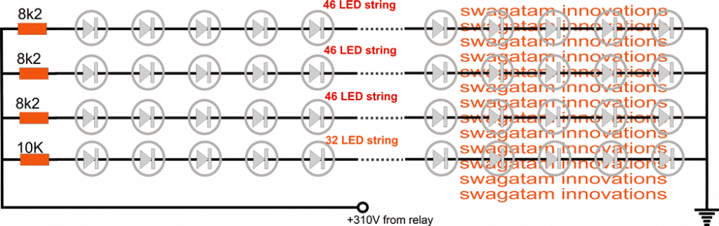
As per the request the welcome sign needs to have 216 LEDs, dividing this 216 with 46 gives us approximately 5 strings, in which 4 strings having around 46 LEDs in series, while the 5th could have 32 LEDs.
Therefore now we have 4 strings of 46 series LEDs and 1 string having 32 LEDs, all these strings now needs to be connected in parallel.
But as we know, in order to allow proper current distribution across the strings and allow uniform illumination, these LED strings need to have calculated resistors in series with them.
Calculating LED Current Limiter Resistor
This can be calculated with the help of the following formula:
R = Supply - Total LED FWD voltage / LED Current
= 310 - (46 x 3.3) / 0.02
here 310 is the DC supply voltage after rectification of the 220V AC supply, 46 is the total number of LEDs, 3.3 is the forward operating voltage of each LED, 0.02 is the current in amps for each LED (20mA), and 4 is number of strings.
Solving the above gives us: 7910 ohms or 7.9K, or simply a standard will 8k2 resistor will do.
wattage will be = 310 - (46 x 3.3) x 0.02 = 3.164 watts or simply a standard 5 watts resistor will do the job
the above 8k2 5 watt resistor will need to be connected with each of the strings having 46 LEDs
Now for the single 32 LEDs, we may have to follow the above procedures separately, as shown below:
R = 310 - (32 x 3.3) / 0.02 = 10220 ohms or 10.2 k or simply a standard 10K will do the job
wattage will be 310 - (32 x 3.3) x 0.02 = 4.088 or again a 5 watts will do.
Circuit Diagram
Through the above formulas we calculated the series parallel connections with resistor for configuring a 216 LED display, however, the above strings will now need to be arranged appropriately in the shape of the alphabets, corresponding to the word "WELCOME". This might require some effort and could be a little time consuming, and might require some patience and skill.
For the second group of LEDs consisting of 696 LEDs, the process will be quite similar. We first divide the 696 with 46 which gives us around 15.13, meaning 14 strings can be configured with a series of 46 LeDs and one string having 52 LEDs...all these strings will likewise need to be connected in parallel and physically arranged to represent the phrase " COLLEGE OF ENGINEERING".
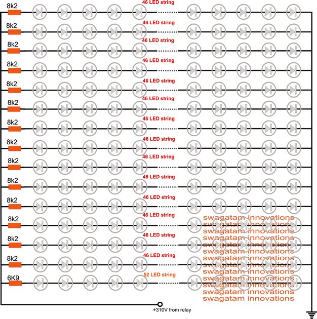
The resistor values for the 46 LED strings can be as calculated in the above sections, while for the 52 LED, it may done as given below:
R = 310 - (52 x 3.3) / 0.02 = 6920 ohms or simply a 6k9 standard resistor may be used.
wattage will be = R = 310 - (52 x 3.3) x 0.02 = 2.76 watts or 3 watts
The above explanation provides us the information regarding how to build any 200 to 400 LED based project for boards or display sign boards using mains voltage without the need of a transformer.
Now, to enable the two sets of LED groups flash alternately using a relay, the following simple IC 555 flasher could be used:
The LED Flasher Circuit
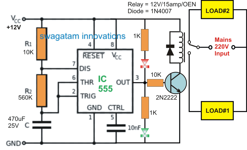
R1, R2, and C can be suitably adjusted for getting the desired blinking rate over the connected 200 to 400 LED strings. The relay does not need to be a 15amp as indicated in the diagram it could be any ordinary 12v 400 ohm 5 amp type of relay


Questions & Answers
can u suggest a circuit for 200 led in series.
Please connect 100 LEDs in series with a series resistor of 500 ohm 2 watt wire wound type.
Replicate the above procedure for the other 100 LEDs also.
Now connect the two strings in parallel.
Supply the AC 220V through a bridge rectifier using 4nos of 1N4007 diodes and connect a series fuse.
I hope you have read the warning message provided in the above article and will abide by it.
Hi Sir,
How many 10 Watt LEB Bulbs can be connected series to the 220volt AC input
Hi Srikanth,
can you please tell me the voltage rating of the LED bulb?
Thank you Mr for information bt In Led flasher I used triac bc134 and it is working
That’s great, thanks for sharing the info.
Dear Mr. Swagatam,
I have a circuit of 24 red led in series (@1,8V, total voltage is 43,2v). The current is limited by 3 x 10K ohm, 2 watt.
The power supply used is transformerless power supply.
I have measured the current and voltage by using AVO Meter. Voltage drop in each resistor is about 48,9V, and the current is 4,9mA. So, the power dissipation on each resistor is about 0,24 watt. It is almost 10
times larger than its rating power (2 watt). But, why does the resistor go hot a few moment after the circuit switched on ?
Please tell me what is the problem ?
Thanks
Dear Izul,
Lets consider the effective resistance to be 30000 ohms 2 watt, so the current limited by this resistance will be:
I = 310 – 43 / 30000 = 0.0089 Amp
Using the power formula gives us:
P = R x I^2 = 30000 x 0.0089 x 0.0089 = 2.37 watts, therefore each resistor is dissipating 2.37 watts, try 5 watts for each resistor.
Thank u sir. So i have made wrong assumption to divide wattage in resistor circuit.
Please make an article about how to determine resistor wattage in variuos circuit, so i can understand the concept of component (resistor in specific) power dissipation.
Thanks
Thanks Izul, In near future I may possibly create an article. Basically it’s the current that decides the wattage. If the current is the same the wattage will be also the same, and not be shared.
Thanks
Based on your calculation, the current flow in 30K resistor is 8,9mA, so resistor will dissipate 2,37watt.
But I divide the resistors become 3x10K, so i’ll get power dissipation of P = I^2 * R = 0,0089 * 0,0089 * 10000 = 0,7921 Watt.
Isn’it enough for the ciruit using 1 watt resistor of 10K ohm for 3pcs ?
Please your advise.
Thanks
By increasing resistance value you are increasing it voltage handling not the wattage, because current is not diving. To divide current/wattge the resistors must be in parallel.
Dear Mr. Swagatam,
Did I make wrong calculation of resistor dissipation ?
I have 3 resistor 10K ohm, the total current flow in series circuit is 4,9mA and the voltage of each resistor is 48,9V. All are based measurement using NDigital AVO Meter I just bought.
Is it possible the false caused by the avo meter ? or i have been wrong to make assumption ?
Please your advise.
Thanks
Hi. I would like to design one led tree with 200, 5mm leds. I can design series & parallels connection.one string having 10 led connected in series & 20 string connected in parallel. Plz help me with a circuit of transformaless power supply for my project. Thank you. I am waiting for you.
Hi, 10 LEDs in series means the total forward voltage required will be around 3.3 x 10 = 33V, and current will be 0.02 x 20 = 400mA
You can buy a 0-24V, 500mA transformer, or a 12-0-12V transformer, and use its outer terminals to connect with a bridge rectifier, and a 1000uF/50V filter capacitor.
Make sure to put a series resistor with each of the 10 LED strings.
The value of the resistors will be 34 – 33 / 0.02 = 50 ohms 1/4 watt each
34 is the peak voltage for a 24V transformer, acquired by multiplying 1.41 x 24.
Hi Swagatam
I want to ask a general question . I found a led driver circuit which produced in China, and the 8 pin IC driver has no any code on it. How can we estimate this ic. This circuit works with directly 220 V. I found some ic led drivers but I am not sure which one. Thanks for your advance.
Hi Mehmet, identifying the exact equivalent of the IC can be difficult, but if you could tell me the rating and the specifications of the circuit, then I can try to produce a mosfet based equivalent.
Hi swagatam. I’m Okey Onah, I really appreciate your efforts to carry us along. Please, i have a project at hand with a rectangular soft board of about 6×2 feet to design a ” WELCOME TO ENERGY CENTER ” display with a total of 620 5mm LEDs which will be mounted at the entrance of the Organization. Through your calculations here, I can design the display board with series and parallels connection, but my major challenge is to design the power supply which will feed the display perfectly without a transformer because the project is too large for transformer to power. Pls help me with a circuit of transformerless power supply suitable for this project. Thank you so kindly in advance, I am waiting to hearing from you soon.
Hi Okey,
the above explained does not require any power supply for the LED strings. The power is taken directly from the 220V mains and then rectified using a bridge rectifier to get the required 310V DC for the LEDs.
Only the IC 555 circuit would required a 12V DC, which could be acquired from a small 12V, 500mA SMPS or from a transformer based power supply
Dear Sir,
I would like to design one led symbol with 200 led with flashing effect .. can you please guide me the best circuit for my requirement ..
thank you sir.
Dear Naveen, I’ll draw the design soon, and let you know…
Sir,
I have a 12v 40A smps supply.what can i do with it at the output (so as to not open the box) to get 5v 40A i.e same current rating.
Plz rply asap.
Nishant, you can try the following concept
https://www.homemade-circuits.com/2015/03/100-amp-variable-voltage-power-supply.html
alright thank u sir
sir, pls kindly give me the complete circuit diagram of a PC based scrolling message display and how to program it. tnx sir
mykb, presently i do not have this circuit, if possible i’ll try to find one and post it for you!
thank u sir, am very grateful. pls another question is that, what can i use to replace LM338 regulator. i saw one of ur post dat u use LM338, i think it can handle upto 50AH battery but dat regulator is so scarce in my area, pls what can i use to replace it in dat same circuit.
Wireless, you can totally avoid the LM338 stage and feed the source supply directly with the opamp stage if you can use a source current that does not exceed the specified rate, or alternatively you can add the following BJT based current controller in the middle:
https://www.homemade-circuits.com/2011/12/make-hundred-watt-led-floodlight.html
gud evening sir, pls i want u to help me wit d circuit diagram of an automatic battery charger using relay, dat can handle 2 or more 12v 7.5AH connected in parallel. pls help me sir.
hello wireless, you can try the first design from the following link, and adjust it for cutting off at 14V
https://www.homemade-circuits.com/2012/07/make-6v-4ah-automatic-battery-charger.html
thanx for the circuit sir, but in dat circuit the last letter E that connected wit d Anode of SCR, the Cathode is not connected to anything.
It seems the connection is slightly wiped off, but it is supposed to be connected with the ground line, all the cathodes are connected with the ground line.
gud day sir, pls kindly give me the circuit diagram of LED that will be display W E L C O M E alphabet by alphabet and also blink all the letters at once 3times. tnx
Hi mykb, you can try the following design
https://www.homemade-circuits.com/2016/09/welcome-chasing-led-display-circuit.html
pls can u help me with circuit diagram of 16 LED and above that will be display in a sequencial form. i.e one by one
just type “18 LED” in the search box, you will get the required circuit
Hello sr please suggest me a circuit ti lit up 10000(ten thousands) led
you can try the following concept
https://www.homemade-circuits.com/2014/04/simplest-100-watt-led-bulb-circuit.html
just go on attaching as many parallel strings as required, make sure to put a small resistor with each string
hi sir i am an aerospace engineer who truley loves your commitment and passion towards exceptional work in helping others.
sir i would appreciate if u can guide me in selecting a surge protected led driver circuit transformerless for 100 watts – 32 volts or 50 watts – 12 volts, as i recently had a burnt led of 50 watts
thank you for your amazing work have been following you for quiet some time now
It's my pleasure Waseem, I think you can try the following concept for your 50 watt LED application, please make sure to upgrade the part values accordingly:
https://www.homemade-circuits.com/2016/07/scr-shunt-for-protecting-capacitive-led.html
Sr how can i make 310 v dc using transformer
If you are using a 12 transformer and if you feed a 12V AC from its 12V side then you might get 220V AC from its 220V side which can be rectified to get 310VDC