The high-voltage neon tube driver circuit discussed in this article generates 500 volts of high-frequency AC (15 kHz). This circuit may be used to brightly illuminate all types of neon tubes.
Neon ranks among the best when it comes to striking, eye-catching lighting displays. Virtually every industry, from pizza restaurants to clothes boutiques, uses neon to draw in targeted customer.
However neon signs could also be employed as a stylish house decoration. Let's take a closer look at how this neon-tube driver functions.

Neon Lamp Working
A neon tube is manufactured by emptying a glass tube with a vacuum pump until a pressure much below atmospheric is reached. The glass tube is then filled with an extremely tiny quantity of neon gas and sealed airtight.
You need to apply a correct source of power to really make a neon tube radiate light. A power source like the one explained here needs to deliver a voltage high enough to ionize the compressed gasses inside the tube.
This process then subsequently energizes the neon gas atoms and generates a dazzling discharge of light. A six-inch neon tube can be efficiently powered by this high-voltage power supply.
How the Circuit Works
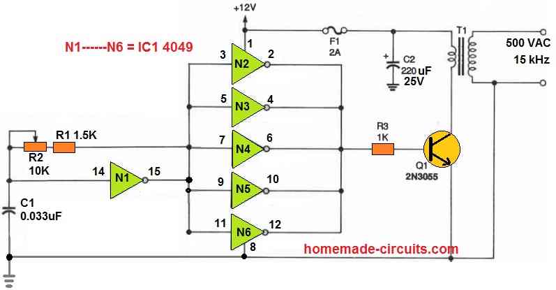
The NOT gate IC (N1 to N6) forms the main part of the circuit. One section of this inverter, N1, is wired to capacitor C1, resistor R1, and potentiometer R2 to produce an oscillator circuit that pulses at around 15 kHz.
The output squarewave from the oscillator will be extremely clean if the IC CD4584 is used, which is a Schmitt trigger.
The frequency could be varied by adjusting R2.
The oscillator's output is delivered to each of the five inverter NOT gates (U1b to U1f).
These NOT gates are coupled in parallel to form a buffer which can boost the oscillator's output current.
The switching transistor Q1 is driven by the squarewave output from the oscillator. Q1 subsequently switches the primary winding of the ferrite-core transformer T1.
The secondary of T1 transformer finally converts the square wave to around 500 volts AC at 15 kHz.
You can use any 12 V 1 amp AC to DC adapter power supply for powering the above neon driver circuit.
How to Test
Take into consideration the following before switching on the device: If you touch the output wires of T1, a High-Voltage Supply output might stun you quite a bit.
Don't ever touch any part of the circuit while the device is powered ON, and use great caution whenever you are near this transformer.
Once the Supply is turned on, you should be able to tell immediately whether it is operating correctly or not according to the application you utilize it for.
If there is an issue, ensure the oscillator section is receiving 12 volts DC from the circuit's power supply. If that isn't, make doubly sure your wiring is installed properly.
Assuming 12 volts are available, use an oscilloscope to investigate pin 8 of U1. There must be a 15 kHz squarewave active. A faulty IC might be the cause if there is absolutely no waveform.
How to Build the Transformer T1
In the article's prototype, transformer T1 was constructed utilizing super enameled copper wire and a pot core. Use a pot core and start winding 500 spins of 30 gauge super enameled copper wire around it to create your homemade transformer.
To maximize space efficiency and increased productivity, wrap the coils in an uniform, straight rotations. Apply an insulating chemical on the secondary once you've finished winding it.
The secondary should then have one or more layers of insulating Adhesive tape applied to it before the primary winding is wrapped over it.
By wrapping 20 rounds of 22-gauge super enameled copper wire over the secondary's insulation, the primary winding is completed.
Application of the Neon Driver
Now that your driver circuit is complete and generating 500 volts of high-frequency AC, what are you intending to make of it? Well, as we just discussed, the Supply's main application is as a source of energy to illuminate a neon tube.
If assembled in accordance with the instructions, the device should have no trouble lighting a 6-inch neon tube.
In the article's prototype, the neon tube was supported by 1/2-inch-diameter PVC tubing, which was also employed to conceal the wiring.
Obviously, you could also carry out high-voltage, high-frequency AC experiments using th is High-Voltage Power Supply in your workshop.
A bridge rectifier may also be added to the transformer T1's output to transform the device into a high-voltage DC power source.
Always keep in mind that excessive voltages are hazardous in any application. So be extremely careful!
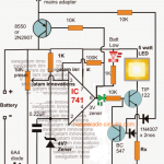
Battery Powered Neon Driver using Step-down Transformer
Are you looking for a cost-effective and straightforward solution for implementing a flashing neon indicator using a battery-powered circuit? This uncomplicated design utilizes readily available components.
Here's how it works: A UJT oscillator generates pulses that drive the base of Q1 through C2.
As Q1 switches on, it causes Q2 to turn fully on, allowing current to flow through the primary winding (usually the secondary) of T1.
This action generates a voltage pulse at the secondary winding of T1, which is sufficient to initiate the neon indicator, causing it to flash.
When Q1 and Q2 turn off (when the pulse reaches zero), the magnetic field produced by the primary current in T1 collapses.
However, D1 is there to short-circuit any back electromotive force (back-EMF) generated, preventing any damage to Q2.
Transformer T1 is an inexpensive step-down type transformer with a 3.5-0-3.5 V secondary winding, a type commonly found in electronics stores. A 9 V transistor radio battery is sufficient to power this circuit.
If you need to control the flasher, turning it on and off as part of another battery-operated circuit, you can easily achieve this by grounding the base of Q1 using either a transistor collector-emitter junction or a gate output.
Grounding the base will inhibit the flasher, while releasing the ground connection will trigger it.


Questions & Answers
I would like to build a power supply for this I know how neon lights work, but I’m not gonna say I really know how to design a circuit for a power supply for neon the power supply they had in here. I copied that I built my own board. It was more of just to see if I could do it than anything. I did get it built. I must’ve built the transformers wrong or something. I guess I really don’t know what went wrong with it, but it was basically a waste of time. Besides the learning experience of building a board from scratch if you can give me any pointers, that would be appreciated. I know you’ll need more info . Please let me know if you can give me some pointers
Thank you, Shad Waldo
Thanks for your question, just wanted to confirm, did you try the circuit explained in the above article?
Or maybe you can explain your design specifications, so that I can design it for you correctly…