In this article I have explained how to calculate LEDs in series and parallel using a simple formula and configure your own personalized LED displays, now you don't just have to wonder how to wire led lights? but actually can do it, know the details here.
These lights are known not only for their dazzling color effects, but also because of their durability and least power consumption.
Moreover LEDs can be wired in groups to form large alphanumeric displays which may be used as indicators or advertisements.
Young electronic hobbyists and enthusiasts are often confused and wonder how to calculate LED and its resistor in a circuit, since they find it difficult to optimize voltage and current through the group of LEDs, required to maintain an optimum brightness.
Why we need to Calculate LEDs
Designing LED displays may be fun, but very often we are just left thinking how to wire led lights? Learn through a formula how simple it is to design your own LED displays.
We already know that a LED requires a particular forward voltage (FV) to get lit. For example a red LED will need a FV of 1.2 V, a green Led will require 1.6 V and for a yellow LED it is around 2 V.
The modern LEDs are all specified with approximately 3.3V forward voltage irrespective of their colors.
But since the given supply voltage to an LED would be mostly higher than its forward voltage value, adding a current limier resistor with LED becomes imperative.
Therefore I have explained how a current limiter resistor may be calculated for a selected LED or a series of LEDs
Calculating Current Limiter Resistor
The value of this resistor may be calculated through the below given formula:
R = (supply voltage VS – LED forward voltage VF) / LED current I
Here R is the resistor in question in Ohms
Vs is the supply voltgae input to the LED
VF is the LED forward voltage which is actually the minimum supply voltage required by an LED for illuminating with optimal brightness.
When a series LED connection is in question, you will just need to replace the "LED forward voltage" with "total forward voltage" in the formula, by multiplying FV of each LED by the total number of LEDs in the series. Suppose there are 3 LEDs in series then this value becomes 3 x 3.3 = 9.9
LED Current or I refers to the current rating of the LED, it may anywhere from 20 mA to 350 mA depending on the specification of the selected LED. This must be converted to amps in the formula, so 20 mA becomes 0.02 A, 350 mA becomes 0.35 A and so on.
How to Connect the LEDs?
To understand this let's read the following discussion:
Let's assume you want to design a LED display having 90 LEDs in it, with a 12V supply to power this 90 LED display.
To optimally match and configure the 90 LED with the 12V supply, you will need to connect the LEDs in series and parallel appropriately.
For this calculation we will need 3 parameters to be considered which are as follows:
- Total number of LEDs which is 90 in our example
- Forward voltage of the LEDs, here we consider it to be 3V for sake of easy calculation, normally this would be 3.3V
- The supply input, which is 12V for the present example
First and formost we have to consider the series connection parameter, and check how many LEDs can be accomodated within the give supply voltage
We do this by dividing the supply voltage by 3 volts.
The answer will be obviously = 4. This gives us the number of LED that could be accommodated within the 12V supply.
However the above condition may not be advisable because that would confine the optimal brightness to a strict 12V supply and in case the supply reduced to some lower value would cause lower illumination on the LED.
Therefore to ensure a lower margin of at least 2V it would be advisable to remove one LED count from the calculation and make it 3.
So 3 LEDs in series for a 12V supply looks good enough and this would ensure that even if the supply was reduced to upto 10V, still the LEDs would be able to light up quite brightly.
Now we would want to know how many such 3 LED strings could be made from our total 90 LEDs in hand? Therefore, dividing the total number of LEDs (90) by 3, we get an answer that's equal to 30.
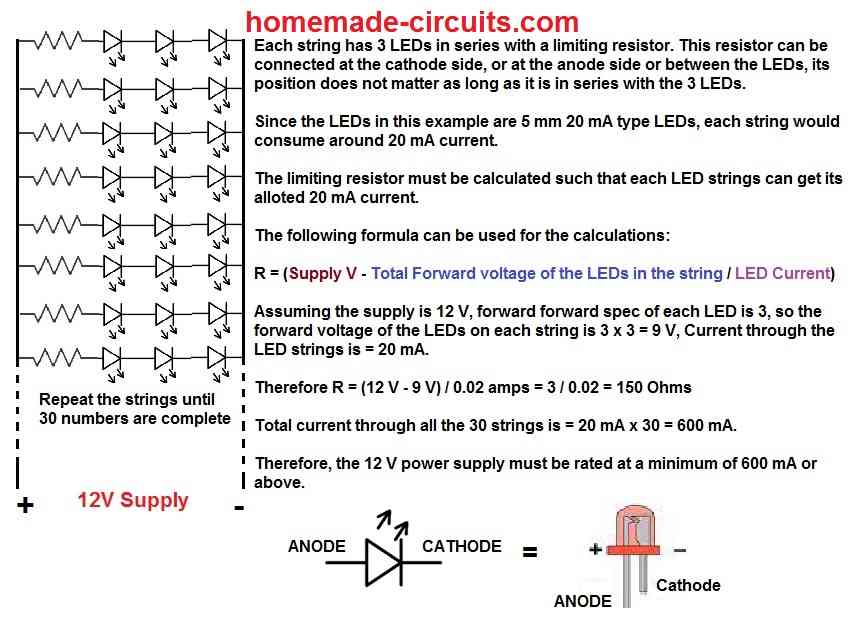
Meaning you would need to solder 30 numbers of LED series strings or chains, each string having 3 LEDs in the series. That's, pretty easy going right?
Once you finish assembling mentioned the 30nos of LED strings, you would naturally find that each string having its own positive and a negative free ends.
Next, connect the calculated value of resistors as discussed in the previous section to any one of the free ends of each series, you can connect the resistor at the positive end of the string or the negative end, the position doesn't matter because the resistor just needs to be in line with the series, you may even include some wher in between the LED series.Using the earler we find the resistor for each LED string to be:
R = (supply voltage VS – LED forward voltage VF) / LED current
= 12 - (3 x 3) / 0.02 = 150 ohms
Let's assume we connect this resistor to each of the negative ends of LED strings.
- After this, you can begin joining the common positive ends of the LEDs together, and the negative ends or the resistor ends of each series together.
- Finally apply 12 volts supply to these common ends as per the correct polarity. You will instantly find the whole design glowing up brightly with an uniform intensity.
- You may align and organize these LED strings as per the design of the display.
LEDs with an Odd Count
A situation may arise when your LED display contains LEDs in odd numbers.
For example, suppose in the above case instead of 90 if the display would have consisted 101 LEDs, then considering 12V as the supply, it becomes a rather awkward task to divide 101 with 3.
So we find the nearest value which is directly divisible with 3 which is 99. Dividing 99 with 3 gives us 33.
Therefore the calculation for these 33 LED strings would be as explained above but what about the remaining two LEDs? No worries, we can still make a string of these 2 LEDs and put it in parallel with the remaining 33 strings.
However to ensure that the 2 LED string consumed uniform current just like the remaining 3 LED strings, we calculate the series resistor accordingly.
In the formula we simply change the total forward voltage as show below:
R = (supply voltage VS – LED forward voltage VF) / LED current
= 12 - (2 x 3) / 0.02 = 300 ohms
This gives us the resistor value specifically for the 2 LED string.
Therefore we have 150 ohms for all the 3 LED strings, and 300 ohms for the 2 LED string.
In this manner you can adjust LED strings having mismatched numbers of LED by introducing a suitably compensating resistor in series with the respective LED strings.
Thus the problem is easily solved by changing the resistor value for the remaining smaller series.
This concludes our tutorial regarding how to connect LEDs in series and parallel for any given number of LEDs using a specified supply voltage, if you have any related query please use the comment box to get it solved.
Calculating LEDs in Series Parallel in Display Board
So far we leraned how LEDs may be connected or calculated in series and parallel.
In the following paragraphs we will investigate how to design a large numerical led display by joining LEDs in series and parallel.
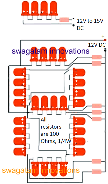
As an example we will build a number display “8” using LEDs and see how it is wired.
Parts Required
You will need the following handful of electronic components for the construction:
RED LED 5mm. = 56 nos.
RESISTOR = 180 OHMS ¼ WATT CFR,
GENERAL PURPOSE BOARD = 6 BY 4 INCHES
How to Calculate and Construct LED Display?
The construction of this number display circuit is very simple and is done in the following way:
Insert all the LEDs in the general purpose board; follow the orientations as shown in the circuit diagram.
Initially solder only one lead of each LED.
After completing this, you will find that the LEDs are not aligned straight and are in fact fixed in quite a crooked manner.
Touch the soldering iron tip on the soldered LED point and simultaneously push the particular LED down so that its base is pushed flat on the board. Do this for all the LEDs to make them aligned straightly.
Now finish soldering the other unsoldered lead of each of the LEDs. Cut their leads cleanly with a nipper. According to the circuit diagram common up the positives of all the LED series.
Connect 180 Ohms resistors to the negative open ends of each series. Again, common up all the free ends of the resistors.
This ends the construction of the LED display number “8”. To test it, just connect a 12 volt supply to the common LED positive and the common resistor negative.
The number “8” should instantly light up in the form of a large numerical display and can be recognized even from long a distance.
Circuit Functioning Hints
To clearly understand how to design a large numerical led display it will be important to know the circuit functioning in details.
Looking at the circuit one may notice that the whole display has been divided into 7 LED series “bars”.
Each series contains a group of 4 LEDs. If we divide the input 12 volts with 4 we will find that each LED receives 3 volts enough to make them glow brightly.
The resistors make sure that the current to the LEDs is limited so that they may last long.
Now by just joining these series LEDs in parallel we can align them into different shapes to produce a huge variety of different alphanumeric displays.
Readers must have now easily understood how to calculate LED in different modes.
Its just a matter of connecting LEDs first in series, then joining these in parallel connections and applying a voltage to their common positives and negatives.



Questions & Answers
Tank you so much Mr. Swagatam
Regards, Gabriel
No problem Gabriel, all the best to you!
Hi Mr. Swagatam
The LED are self flashing
Power supply to be used: 24 V
Integrated IC versions: 3.3V – 5.0VForward Current: 15mA (typical) / 20mA (maximum)Flashing Frequency: 1.0Hz – 1.5Hz (approx. 1 to 1.5 flashes per second)Viewing Angle: 120 degrees Built-in Circuitry: Internal multi-vibrator / blink controller IC (no external blinking code or 555 timer required)
Thanks Gabriel, for the information.
You can connect the LEDs in the following manner.
Make 20 strings of red LEDs, each string having 10 LEDs in series with a series 100 ohm 1/4 watt resistor.
Make 10 strings of flashing LEDs, each string having 6 LEDs in series with a 220 ohm 1/4 wat resistor in series.
Connect all these strings along with their resistors in parallel with each other and connect the parallel ends with 24V DC supply
Hi Mr.Swagatam
Please help me with a circuit diagram for 220 red smd LED 402 and 60 withe smd LED 805
The 805 are the flashing type
Thank you
Hi Gabriel,
what are the forward volt specifications of the LEDs, are they 3.3V? Please let me know, then will suggest…
Hi Mr. Swagatam
The 220 red led forward volt specification 2.0 -2.2 V
The 60 white led forward volt specification 3.0 – 3.7
Gabriel, Please give more information, you said flashing type LED, meaning LEDs are itself flashing or you want external flasher for that, what should be the power supply type, and also the voltage range?
Hello dear Swagatam, l’m going to make a diy light for mobile video recording that will fix on a rig. My plan is use two 18650 rechargeable batteriy cells with 3400mah.
My question is 2 parts.
First, is it possible to light up 64 5mm (3~3.2v , 15~20 mA) LEDs with that power supply?
Second, as you taught I have to make series groups and then paralleled them. Batteries supply 7.4v . So I have to make 2 LEDs in series with a resistor, right?
I hope my questions are clear.
Hi S.M.
Yes, it is possible to light up 64 5mm (3~3.2v , 15~20 mA) LEDs using two 18650 rechargeable cells in series.
So assuming the cells ate connected in series, then the optimal output voltage would be around 8V.
That means we can accommodate a string of two 3.3V in series with a resistor.
So for 64 LEDs, it would be possible to hook up 32 such strings in parallel with the 8V 3400mAh source.
Assuming the LEDs are 20mA rated, each string would consume 20 ma, meaning the total 32 strings would consume around 20 * 32 = 0.64 amp current, which is well within the max range of 3 amp current from the battery.
The series resistor for each LED string can be calculated as follows:
R = (Supply input – LED Total FWD drop) / LED Current
= 8 – 3.3 * 2 / 0.02
= 8 – 6.6 / 0.02 = 70 ohms
Power = 0.028 watts or 1/4 watt.
Thank you for replying such soon,
So as i searched the nearest standard resistor to 70 ohms is 68 ohms 1/4 w +- 5%
Is it a right choice?
It’s my pleasure!
Yes, 68 ohms 1/4 w +- 5% can be used, but I would recommend using higher than 70 ohms, not lower. So maybe an 82 ohms would be more preferable.
Hello, I’m going to make a DIV nail polishing curing lamp, which will contain 30 led bulbs, with following manufacturer data:
1) Wavelength: 375nm
2. Power: 3W
3. Forward Current: 600-700mA
4. Forward Voltage: DC3.2-3.6V
I’m going to place each led bulb on the 20mm*1mm round PCB Aluminium plates and then place then on the larger aluminum heat sink. Which wiring method and power supply would you recommend?
Would be glad to receive your advice.
Hi, thanks for the interesting question:
A 3W LED would normally consume around 900 mA, so for 30 LEDs, you would require a total current of 900 * 30 = 27 Amps, that’s a lot of current.
You will need a regulated constant voltage, constant current DC output for your LEDs, which can be achieved using the following basic voltage regulator circuit:
https://www.homemade-circuits.com/wp-content/uploads/2021/01/regulated-power-supply-basics.jpg
For T1 you can use the transistor MJ11028:
https://www.onsemi.com/pdf/datasheet/mj11028-d.pdf
T2 can be a 2N2222 BJT
T3 can be also a 2N2222 BJT.
VR1 can be a 10k preset or trimpot.
R2 = 0.7 / 25 = 0.025 Ohm resistor (power will be 0.7 * 25 = around 20 watts
Input DC can be from a a 6V or 9V 30 amp DC power supply
Diode d1 is not required and can be replaced with a short.
Let me know if you have any further questions.
Thank you for your quick response. I didn’t expect that transistor and resistor would need to be implemented manually for my case; wouldn’t the power supply (according to your recommendation, I found one from aliexpress AC 220V to 9V 30A 270W DC) already be self regulating?
2) on your circuit scheme – where are the 30 PCs led bulbs, and how should they be wired?
Regards
Mark
I am not sure whether your power supply is self regulating or not, if it can automatically adjust the output to 3.3V, 25 Amps then there’s no need of any external regulator circuit.
In the suggested regulator circuit, the LED must be connected at the “+DC OUT” side.
All the LEDs can be wired in parallel.
For extra safety you can add a 1 ohm 1 watt resistor in series with each LED.
Thank you for your reply. May I add you on telegram (my account @mark25mark) or WhatsApp (+4917685699047) and show you the foto of the planned power supply unit? I would appreciate if I could consult you on this way where I can show you pictures.
regards
Mark
Could you please send the pictures to my email?:
homemadecircuits
@gmail.com
I will check it and let you know my opinion here.
if i connect 1.2 volt 10 led in series circuit with 12 volt line, then can i avoid using register in circuit???
Yes, then you can avoid the resistor, however the 12V must not exceed at any cost.
Hello Swagatam, I built a doll house for my daughter. I would like to use small fairy LEDs to light and decorate it. During Christmas I purchased a roll of fairy lights on very thin silver wire. The lights are about the size of a grain of rice. The package says the string can be cut to length, but it has to be used with the battery pack that comes attached. I need to cut several 3-light, 4-light and 5- light pieces out of the string. How do I wire each of these different light sections? I believe I need a resistor, but I do not know the voltage or current requirements for the LEDs. I would like to use a 9 volt battery to power the lights, but I am open to whatever you may suggest. Thanks!
Hi Doran, if the package says the string can be cut to length, that means each LED could be having its own individual resistor in the string, otherwise cutting the strip into any desired length might be impossible. So I guess the pieces can all be wired in parallel with the supply voltage. You can try connecting the 3 LED strip with the 9v battery and check the response, if it illuminates normally that would indicate my assumption is correct. If you do not wish to take any risks, then you can try connecting a 470 ohm resistor in series and check the brightness level, and keep adjusting the resistor value until the LEDS illuminates optimally. I would also rather recommend using a 3v DC source first without any resistor that would quickly clarify the minimum voltage level of the string…if it does not illuminate the LEDs you can go a little higher and keep doing this until the right voltage level is identified…
Dear Mr. Engineer Swagatam,
I am working on my first modling kit of a Spacecraft and am trying to light it. I wanted to use both LED strips in series, but I also wanted to put in slow and reg blinking LEDs to a total of 24. I have a 12V imput.
I found a site that sells 3v LEDS that (even in different colors) that blink and don’t blink respectively, but all are 3V exactly. I also found the same LED lights in 12V. So here’s my question. If I use the 3V and put them in parallel rows of four then I wouldn’t require any resistors? But Could I put them into the same circuit as the LED strips and just split the wire right off the battery source or at any split between LED Strips?
Or Could I just attach the 12V LEDs at the end of any LED Strip and the number wouldn’t matter because they are 12V like the strips themselves?
I’ve soldered just LEDS before, and just LED strips, before but never tried to combine them without a microchip of some sort, but I wouldn’t know the exact way to do that either. Any info to help would be greatly appreciated!
Thanks Vonelle for posting this question.
Since, the 3V LEDs can be illuminated using 3V supply and also from 12V, that means the LEDs have built-in voltage regulator, and is safe to drive from a 12v dc supply. Therefore you can connect these LED modules using 12v dc at any position in the circuit, you can take the supply directly from the battery terminals or from the end of the existing 12v led strips, it does not matter as long as the 3v LED modules are getting the 12v supply or any supply above 3v.
HELLO SWAGTAM, IN ABOVE EXAMPLE U HAVE REDUCED THE NUMBER OF LED FROM 4 TO 3 IF THE BATTERY VOL COMES DOWN. AS FAR AS I KNOW A FULLY CHARGED 12V BATTERY IS AROUND 14.3 V. 3*3.2 V = 9.6V . WILL THE 3 LEDs NOT get DAMAGED.I HAVE DONE THIS PRACTICAL. LEDs GOT DAMAGED..SO PLZ DONT ASSUME ANYTHING ESPECIALLY WHEN IT COMES TO ELECTRICAL CIRCUITS.
ALSO U DONT GIVE VALUE OF ALL RESISTANCES IN MANY POWER SUPPLY CIRCUITS. PLZ GIVE FULL DETAILS SO THAT EVERYONE COULD BENEFIT.
Hello Sanjeev,
May I ask why you have written in capital letters?
A fully charged 12V battery when disconnected from the charger will settle down to around 12.8 V, and not 14.3 V.
LEDs can never get damaged if a calculated resistor is used in series.
And I have clearly given the formula to calculate the resistor, so the LEDs can never burn with a resistor connected.
I always give values of all parts in my circuit diagrams. What you are saying is incorrect.
Good day MR Swagatam.
I have a pcb with 8 smd leds connected in series. leds are 5 x 3 mm in size. These leds are powered from a 6 volt 4A/h sla battery with no current limiting resistors on the pcb( I have checked on the charger pcb to, negative runs straight from the battery to the led pcb and positive runs from the battery through a dpdt switch to the led pc ). This circuit comes from an old emergency light with a dead battery and broken charger circuit. How can I determine the vf and mA for these leds as I would like to use this pcb to make a work light for my small milling machine. I have used a battery from another emergency light with the exact same model number as the light that I obtained this pcb from and when I connect the battery to the pcb the leds light up fairly bright and the pcb warms up fairly fast and I think it is because of no current limiting resistor. I want to power my work light from a 220 volt AC to 6 volt DC wall plug smps. I would like to add current limiting resistor so that the leds does not run so hot and can last longer. There is no markings on the leds or the board so that is why I need to know if there is a way that I can determine the vf and mA rating for each individual led so that I can calculate the current limiting resistor value. If I try to remove one led from the board, I will destroy it, so I will only be able to test with all the leds connected in series.
Thank you.
Hello Ian,
You can try the following procedure:
Connect a relatively high value resistor such as 1K and connect it in series with one of the supply wires of the LED module.
Next, take a variable power supply and adjust its voltage to around 3V and feed the supply to the LED module through the 1k resistor.
If you find the LED module glowing with some minimum brightness that would mean that the module is rated at 3.3 V.
In this situation you can bypass the 1K resistor with a short link. If this makes the LED much brighter would confirm that the module is rated at 3.3V.
Next connect an ammeter and check the current of the module to find the optimal current requiremeent of the module.
If the module does not glow at 3V, make sure not to remove the 1k resistor and keep increasing the voltage very slowly until the module starts glowing with some minimum brightness.
Repeat the procedure which was done for the 3V indication.
Hi! I have about 150 leds to connect and make a word “SALON”. Can i use 12v dc or not and why. Best regards
Yes you can do it with a 12 V supply, by creating strings of LEDs, having 3 LEDs on each string with a limiting resistor.
Hello sir how r u
Sir I want to run 100 led of 3.3v in parallel connection to 230v ac so u have any circuit for that
Hello Basit, you will have to use an SMPS circuit for this.
Assuming the current rating of each LED is 20mA, then for all the 100 in parallel the current wuld be 2 amps.
So you might need an SMPS circuit rated at 6V 2 amps or 12V 2 amps, then use the following formula for calculating the limiting resistor which must be connected in series with each LED
R = SMPS Voltage – 3.3 / 0.02
Hi, my friend!
I want to use LEDs as a brake light (3-5watt) for a car. Is it possible to use a diode with the following characteristics:
SMD5730
0.5Вw 3-3.4V 150mA
The use of a quenching resistor is not possible due to its large power and size.
I looked at the diagrams on voltage stabilizers, but so far I can’t correctly calculate the parameters of such stabilizer for SMD5730.
What can you advise in this situation? Perhaps you know the wiring diagram?
Yours faithfully, Jorge
Hi, friend, are you trying to make a 5 watt LED using 150 mA LEDs by connecting them in series and parallel? For this you will need series resistors and also a LM338 current regulator.
Thank you, my friend Swagatam!
I’ll try to use LM2596 as current regulator for LED. Or maybe MT3608 module.
I think that I will not need limiting resistors if I use a current regulator with a pre-set operating voltage for the LEDs in parallel.
After my experiments, I will definitely write a short report. I think it will be useful for many users.
You are most welcome Jorge,
Yes no resistor will be required if the current is set correctly, and if the input voltage is exactly equal to the recommended forward voltage of the LEDs.
All the best to you.
Vs = 1.2 volts
red led forward voltage = 1.6 volts
I = 10mA
r = to be determined below
1.2 – 1.6 / .01 = (-158.8)
So, I need to use a -158.8 resistor? I don’t think such a thing exists. What do I do?
Operating a 1.6 V LED with 1.2 V also doesn’t exist.
…Use a joule thief circuit
Thank you for your advice…