Today I am showing you how to make very powerful pen style electric arc metal engraver circuit using IC 555 and MOSFET.
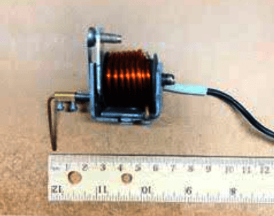
Actually this idea is inspired by one of my blog reader, and my friend Mr. August. He made one crude engraver using 6V transformer and tractor charging coil, but he wanted a smooth pen style engraver to write dark letters on metal using electric sparks instead of noisy mechanical vibration. So I designed this easy solution for everybody.
Audio/Video Representation
Here's the original email from Mr. August:
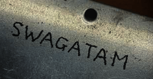
Hi Swagatam, I am hoping that you can help me to make a better engraver than the crude one that I have built using a 6v transformer and a coil from a tractor charging system regulator. Attached is a demo of engraving over pencil lines on metal. What I would prefer but don’t have the design knowledge is more of a pen like stylus driven by either pulsed a.c. through a triac to the stylus or PWM through a MOSFET to the stylus, similar to an IGBT inverter welder. I hope that you have a suggested design for me. Regards, August.
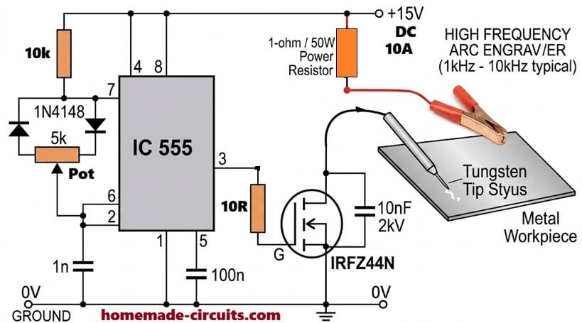
Based on the above suggestions by Mr. August, I designed the following simple 555 pwm MOSFET driver circuit:
How Circuit Works
Main component here is IC 555 which is connected as PWM oscillator. It runs at high frequency around 1kHz to 10kHz depending on 1nF capacitor on pin 2 and 6.
The two 1N4148 diodes and 5k pot will change the ON and OFF time duty cycle. When you rotate 5k pot, it adjusts the spark power. Turn it low for fine thin lines, turn high for deep dark etching on metal.
Output pin 3 of IC 555 goes to Gate of IRFZ44N MOSFET through 10 ohm resistor. Very important tip here, do not use big resistor like 470 ohm because MOSFET will become boiling hot fast! 10 ohm gives super fast switching so MOSFET stays cool and gives strong arc sparks.
Across Drain and Source, one 10nF 2kV high voltage capacitor is connected to save MOSFET from reverse voltage spikes when spark breaks.
Power supply is +15V DC 10 Amp. The positive line connects to 1 ohm 50W heavy resistor. This resistor is compulsory for current limiting, otherwise power supply will short circuit when tungsten tip touches metal. From 50W resistor, red wire with crocodile clip attaches directly to metal plate.
Drain pin of MOSFET connects to thin stylus pen. Inside stylus, one sharp tungsten rod is fixed. When you touch tungsten point on metal workpiece, thousands of tiny high frequency electric micro arcs burn the metal surface smoothly so you can write like normal pencil without any heavy vibration.
Parts List
IC 555 - 1 piece
IRFZ44N MOSFET with big heatsink - 1 piece
1N4148 Diodes - 2 piece
10k Resistor - 1 piece
10 Ohm Resistor - 1 piece
5k Potentiometer - 1 piece
1nF Ceramic Capacitor - 1 piece
100nF Ceramic Capacitor - 1 piece
10nF 2kV Capacitor - 1 piece
1 Ohm 50 Watt Wirewound Resistor - 1 piece
15V 10A DC Power Supply Crocodile Clip and Tungsten Rod for Stylus
How to Build and Test
First assemble IC 555 parts on small zero PCB. Put MOSFET on heavy heatsink. Use thick copper wires for 15V line, 50W resistor, clamp, and stylus line because current is high.
Make stylus handle using plastic pipe so hand does not burn. Connect 15V supply, clamp crocodile clip on metal plate, keep 5k pot at middle, and slowly write on metal using tungsten tip.
Adjust pot for the best sparks.
If any doubt or question is there, please ask in comment box below!
I am an electronics engineer and doing practical hands-on work from more than 15 years now. Building real circuits, testing them and also making PCB layouts by myself. I really love doing all these things like inventing something new, designing electronics and also helping other people like hobby guys who want to make their own cool circuits at home.
And that is the main reason why I started this website homemade-circuits.com, to share different types of circuit ideas..
If you are having any kind of doubt or question related to circuits then just write down your question in the comment box below, I am like always checking, so I guarantee I will reply you for sure!



Need Help? Please Leave a Comment! We value your input—Kindly keep it relevant to the above topic!