In this post I will show how to construct a digital clock using 7 segment LED display with Arduino controlled design.
How the Circuits Works
The proposed 7 segment clock circuit is inexpensive and even beginner in Arduino can accomplish it with ease. This clock consists of four 7 segment displays, two for hours and two for minutes.
The display is paired with IC 4026 which is designed for driving 7 segment displays. Each IC 4026 is controlled by Arduino.
This clock has beep alert function, which beeps every beginning of the hour, giving a rough idea about time without looking at the clock. This clock does not have alarm function.
The Arduino code doesn’t need any special library for compile the program. The clock has very minimalist design, just four displays and two LEDs for AM/PM indicator and no fancy functions other than beeping every hour.
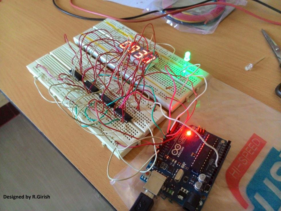
Author’s prototype:
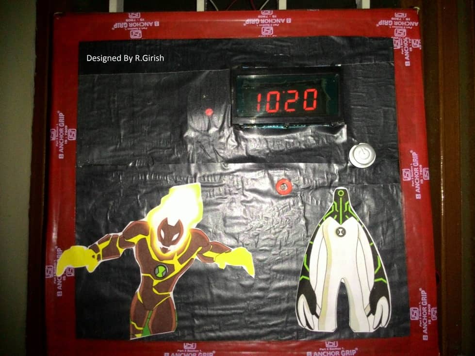
Here is a completed prototype using cardboard and scrap materials:
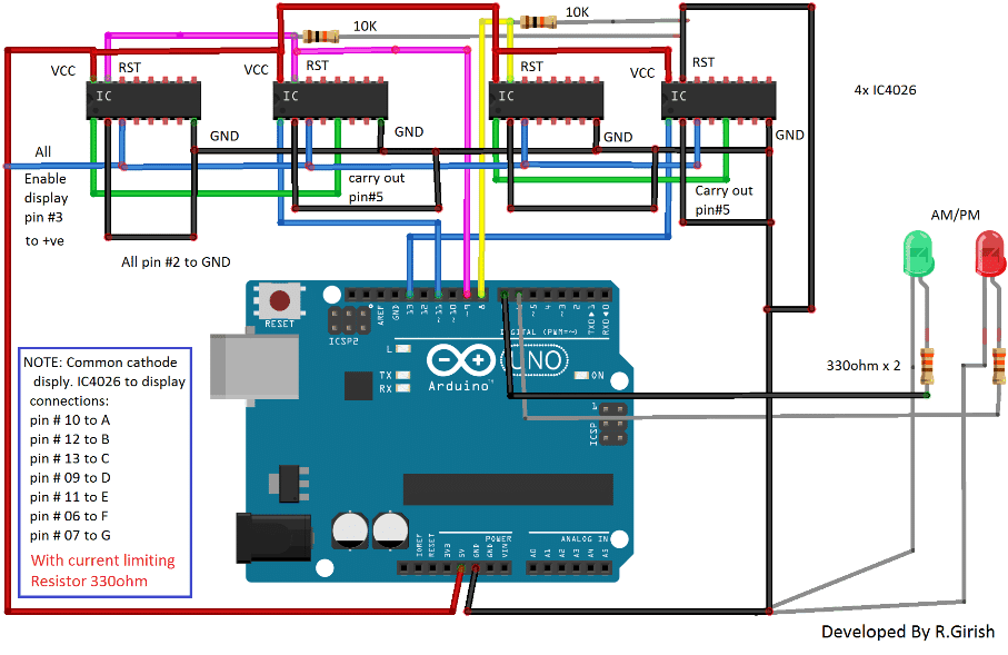
The Design:
The circuit consists of four IC 4026 for controlling four 7 segment displays and the brain of the clock arduino. Two pull down resistors are connected to reset pin of IC 4026 to avoid accidental reset due to static charge. AM/PM indicator connected to arduino in combination with 330 ohm current limiting resistor.
Note: 220 ohm to 330 ohm resistor should be connected each segments of display.
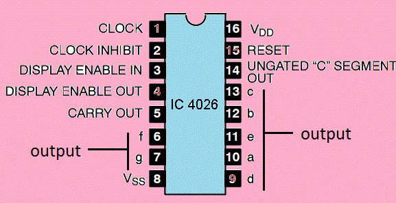
Pin configuration of IC 4026:
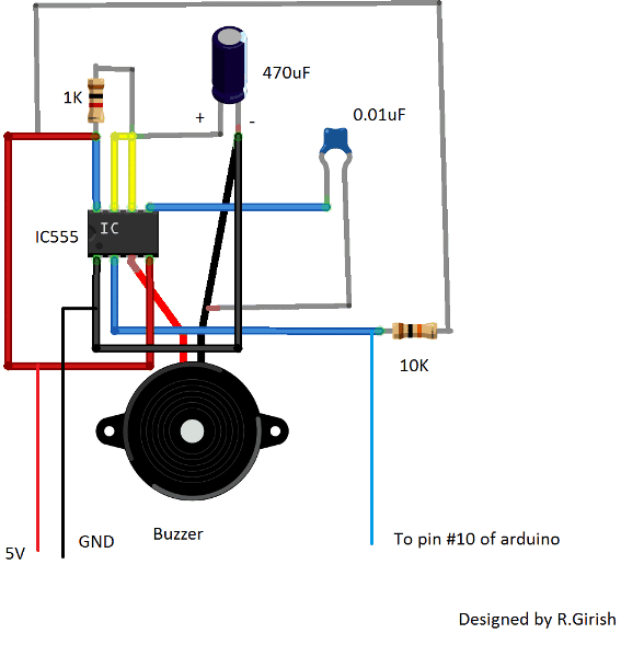
The beeper circuit:
The beeper circuit is just a monostable multivibrator designed using IC555. When a negative pulse is fed to pin #2 of IC555, it beeps roughly for one second. This audio alert helps the user to keep a rough idea about the time. The pin #2 of IC555 should be connected to pin # 10 of arduino.
Program Code:
//---------Program developed by R.Girish---------------//

int mint=13;

int hrs=11;

int beep=10;

int rst=8; // reset to mint ic.

int rsth=9; //reset to hrs ic.

int am=7;

int pm=6;

int y=0;

int t=0;

int x=0;

void setup()

{

pinMode(beep,OUTPUT);

pinMode(hrs,OUTPUT);

pinMode(am,OUTPUT);

pinMode(pm,OUTPUT);

pinMode(mint,OUTPUT);

pinMode(rst,OUTPUT);

pinMode(rsth,OUTPUT);

}

void loop()

{

digitalWrite(beep,1);

digitalWrite(13,0);

delay(10000);

delay(10000);

delay(10000);

delay(10000);

delay(10000);

delay(10000);

digitalWrite(13,1);

t=t+1;

if(t==60)

{

digitalWrite(rst,1);

digitalWrite(rst,0);

digitalWrite(hrs,1);

digitalWrite(hrs,0);

digitalWrite(beep,0);

digitalWrite(beep,1);

x=x+1;

y=y+1;

t=0;

delay(2000);  // error fixing (varies with temperature)

}

if(x==13)  // display 1'O clock after 12'O clock.

{

digitalWrite(rsth,1);

digitalWrite(rsth,0);

digitalWrite(hrs,1);

digitalWrite(hrs,0);

x=1;

}

if(y<12)

{

digitalWrite(am,1);

digitalWrite(pm,0);

}

if(y>=12)

{

digitalWrite(pm,1);

digitalWrite(am,0);

}

if(y==24) y=0;

}

//---------Program developed by R.Girish---------------//
How to set time:
Being very minimalist design the “reset button” can be used to set time. But the user has to set the time with the help of reference clock. The user has to reset the arduino at exactly 12’O clock. One this is done the clock updates the time on its own.
Note: Since the above explained 7 segment digital clock using Arduino does not have “real time clock chip”, for maintaining accurate time, there is possibility that the time may lead/lag due to change in the ambient temperature.
To rectify this here are the steps:
• If your clock leads the time of reference clock by few seconds it need to be slow down, note down the difference and enter the value in the program in milliseconds.
delay(2000); // error fixing (varies with temperature) This will slow down few seconds every hour.
• Replace 2000 with your value.
• If you clock lags set the “delay(0); //error fixing(varies with time)” and make the following changes in the program:
delay(10000);

delay(10000);

delay(10000);

delay(10000);

delay(10000);

delay(10000);

to

delay(10000);

delay(10000);

delay(10000);

delay(10000);

delay(10000);

delay(9700);
Replace “delay(9700);” with your value to speed up the time every minute.
These steps do not guarantee that time will be always accurate, but it helps to maintain the time with minimal inaccuracy. The proposed design is 12 hour clock.



Questions & Answers
Sir ? Please help me I have to make 7 segment display project using ic 7447 I know it’s a basic one but I couldn’t get the circuit diagram so it’s difficult for me !
Hello Naina, you can try the following circuit:
https://www.homemade-circuits.com/wp-content/uploads/2025/07/7447-counter-circuit-e1752050316964.jpg
And can I add push botton instead of dip switchs because 7490 can count for me ! If yeah then how to add ?
You can try the circuit from the following article, with SPDT switches:
electronics-formulas.com/explained-7-segment-display-counter-circuits/
Sir I got it Understanding the Single Digit 7-segment Display Counter is this one which have push button function but circuit diagram of it is a bit confusing for me ! Can you make a simplified version of this single digit 7 segment display? For me please 🥺 one with more simplified connections ! And I’m beginner and it’s my collage assignment so please help me sir
Naina, you can try the previous diagram with a push button attached:
https://www.homemade-circuits.com/wp-content/uploads/2025/07/7447-LED-driver-circuit-using-push-button.jpg
Okay that’s means I have to use 220ohm resistors! Okay 👍🏻
Correct, you got it 👍🏻!
Sir resistors value ? And pinouts of the display!
Naina, please check this diagram, all the details are given in it:
https://electronics-formulas.com/wp-content/uploads/2025/01/Single-Digit-7-segment-Display-Counter-circuit-1024×374.jpg?v=1737462647
What’s the resistance value of the R1 to r7 ? And at which pin should I connect them at display? There’s no mention of the displays connection and pinout !
Sir displays connection is a bit confusing can you simplify it ? And what’s u2(cka) ? And did I have to use 2 ic ?
You can try the following circuit instead of the previous one:
https://www.homemade-circuits.com/wp-content/uploads/2025/07/7447-LED-driver-using-DIP-switch.jpg
Sir what’s the specifications of this circuit means should I have to use 1k resistors and dip switchs that’s all ?
Naina, yes you can use 1k pull-up resistors in series with the DIP switches, as you change the switch connections, you will see the appropriate figure on the display.
No sir it didn’t worked I have done all the connection rightly but still display didn’t light up ! Even I’m giving it 5v still nothing is happening I have connected 1led with dip switchs and resistors it worked but not the display I even changed ic !
Please do the connections as per the following circuit, it will work 100%
https://electronics-formulas.com/wp-content/uploads/2025/01/the-74LS47-Decoder-Circuit-1024×426.jpg
Oh no I have not added 220 ohm resistors between 7447 to display do I have to ?
In this new diagram you have to add, but not in the earlier diagram, because the earlier diagram has a common R2 with the display negative supply…
And should I add R1 resistor also ?
Please do it exactly as given in the last diagram, which I suggested today.
Then why shouldn’t I add R2 resistors but it’s not negetive it’s in the positive line and what’s the value of the R2 resistor ! It will be much more easier then adding bunch of 220 ohm resistors isn’t it ?
If you add a single resistor then the display light will get weaker and weaker as more digits illuminate and thus the illumination of the digits will not be uniform…
So instead of adding R2 resistor I have to add 220 ohm resistors between ic and display! That’s all nah ?
Yes, that’s right, to ensure the display gets a uniform illumination for all digits…
Nope sir I have added 220ohm resistors but still display didn’t light up why ?
Naina, please check if your display is common-anode or not. If it is common-cathode then it will not work. You can put series LEDs with 220 ohm resistors to check if the outputs are producing the required voltages or not.
I have checked the output voltage and its only 1.9 or .8 or .9 in all the pins without even switching dip switchs!
Connect LEDs between positive supply and the the IC output pins through resistors, and then switch ON the switches and check the response…
Yeah sir working but even if the switches is off leds are on there 4.8v and 3.8 v at some pin some leds are dim and some are fine how ? That’s means ic is faulty and display also ?
If you have used 5V correctly for the IC, then the IC could be possibly faulty. You can check the display separately by connecting its common anodes to positive and then joining the other pins with ground through a 1k resistor. If the display lights up then the display is ok…
Sir can I swap 7448 ic ? Because it’s a chathod one ! Do I have to change any pinouts ?
IC 74LS47 and 7447 are one and the same and have exactly identical pinouts, only the supply range is different 74LS47 requires strict 5V to operate while 7447 can be used with voltages upto 15V. So no, that won’t work. Please change your display.
Sir I have bought common chathod display 😥😢 what should I do now ? Because in the output pins of the ic I get signals in nagative line and this display works on postive line and com chathod !
Naina, that’s what I told you in my previous comment, to check the display specs. Common cathode will not work here, it should be common anode. And that’s why your circuit is not working…
And what’s the value of R1 and r0 is 1k ?
R1 is not required, you can connect +5V directly to that point. R0 can be all 1k…
Sir I’m using 10 switch dip switchs so can this work ? And if yeah then where to connect rest of the 6 switchs ? And I have to use normal 1k resistors to all the switches?
You can keep the remaining switches unused and unconnected. Yes, use standard 1k 1/4 watt 5% resistors.
Sir just like this in this circuit diagram you can easily point out which connection is made to which pin so that’s perfect can you make like this ? It’s the most simplified version I have ever see all we have to do is add 7490 and push botton! Thanks for helping sir 🥺
You are most welcome Naina, glad it helped you!
Naina, you can find all the details in the following article, in the 3rd diagram from top:
https://electronics-formulas.com/explained-7-segment-display-counter-circuits/
Sir this is still confusing my mind is getting blasts I need to complete this project and submit it within 2 days can you please provide me completely mentioned connection and simplified version of this push botton function 7 segment display project? 😭😭😭😭😭 Please 🥺 🙏🏻
Hello Naina,
The pin connections are clearly shown in the diagram, right? So you just have to follow the diagram and write it down as per the given connections.
You sound exactly like Mr. Neeraj, another avid reader of this blog 😀