In this post I will show how to construct a car robot which can be controlled using a joystick on 2.4 GHz wireless communication link. The proposed project is not only made as a RC car, but you can add your projects such as surveillance camera etc. on the car.
Overview
The project is divided in to two parts; the remote and the receiver.
The car or the base, where we place all our receiver components can be three wheel drive or four wheel drive.
If you want more stability for the base car or if you want to drive the car in uneven surface such as outdoors then, car base with 4 wheels are recommended.
You can also use 3 wheel drive base car which give you greater mobility while turning but, it may provide less stability than 4 wheel drive.
A car with 4 wheels but, 2 motor drive also feasible.
The remote may be powered with 9V battery and receiver may be powered with 12V, 1.3 AH sealed lead acid battery, which has smaller footprint than 12V, 7AH battery and also ideal for such peripatetic applications.
The 2.4 GHz communication between is established using NRF24L01 module which can transmit signals over 30 to 100 meters depending on obstacles in between two NRF24L01 modules.
Illustration of NRF24L01 module:

It works on 3.3V and 5V can kill the module so, care must be taken and it works on SPI communication protocol. The pin configuration is provided in the above image.
The remote:
The remote consists of Arduino (Arduino nano/ pro-mini is recommended), NRF24L01 module, a joystick and a battery power supply. Try to pack them in a small junk box, which will be easier to handle.
Schematic diagram for remote:

The pin connections for NRF24L01 module and joystick is provided in the diagram, if you feel any muddle, please refer the given pin connection table.
By moving the joystick forward (UP), reverse (Down), right and left, the car moves accordingly.
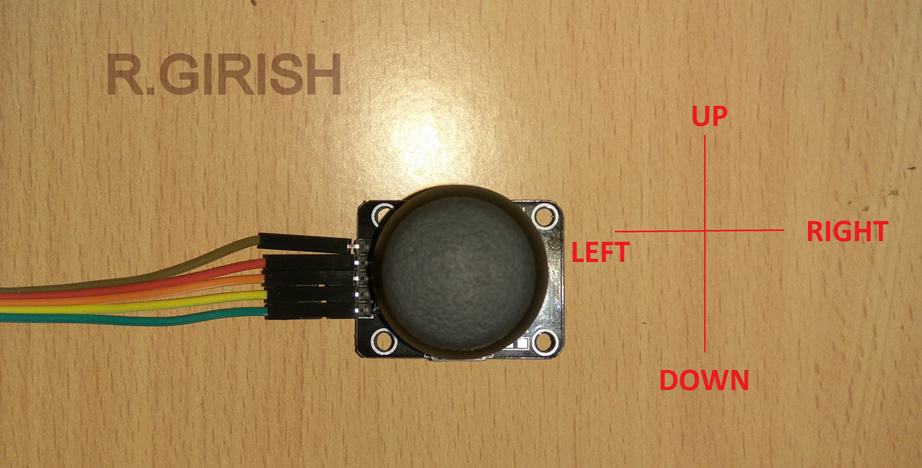
Please note that all the wire connections are at left side, this is the reference point and now you can move the joystick to move the car.
By pressing the joystick in Z axis you can control the LED light on the car.
Program for the Remote:
#include <nRF24L01.h>
#include <RF24.h>
#include <SPI.h>

RF24 radio(9, 10);
const byte address[6] = "00001";

int X_axis = A0;
int Y_axis = A1;
int Z_axis = 2;

int x = 0;
int y = 0;
bool button = false;
bool lightState = false;

unsigned long lastToggle = 0;

int deadzone = 40;  // joystick stability zone

struct Payload {
  int xVal;
  int yVal;
  bool light;
};

Payload data;

void setup() {
  Serial.begin(9600);
  pinMode(X_axis, INPUT);
  pinMode(Y_axis, INPUT);
  pinMode(Z_axis, INPUT_PULLUP);

  radio.begin();
  radio.openWritingPipe(address);
  radio.setChannel(100);
  radio.setDataRate(RF24_250KBPS);
  radio.setPALevel(RF24_PA_LOW);
  radio.stopListening();
}

void loop() {

  x = analogRead(X_axis);
  y = analogRead(Y_axis);
  button = digitalRead(Z_axis) == LOW;

  // joystick deadzone
  int xMid = 512;
  int yMid = 512;

  if (abs(x - xMid) < deadzone) x = xMid;
  if (abs(y - yMid) < deadzone) y = yMid;

  // toggle light using non-blocking method
  if (button && millis() - lastToggle > 250) {
    lightState = !lightState;
    lastToggle = millis();
  }

  // pack data
  data.xVal = x;
  data.yVal = y;
  data.light = lightState;

  // transmit struct
  radio.write(&data, sizeof(data));
}
That concludes the Remote.
Now let’s take a look at the receiver.
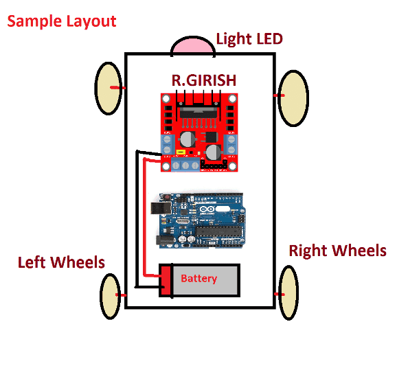
The receiver circuit will be placed on the base car. If you have any idea to add your project on this moving base, plan the geometry properly for placing the receiver and your project so, that you don’t run out of room.
The receiver consists of Arduino, L298N dual H-bridge DC motor driver module, white LED which will be placed at front of the car, NRF24L01 module, and 12V, 1.3AH battery. The motors might come with base car.
Schematic diagram for receiver:
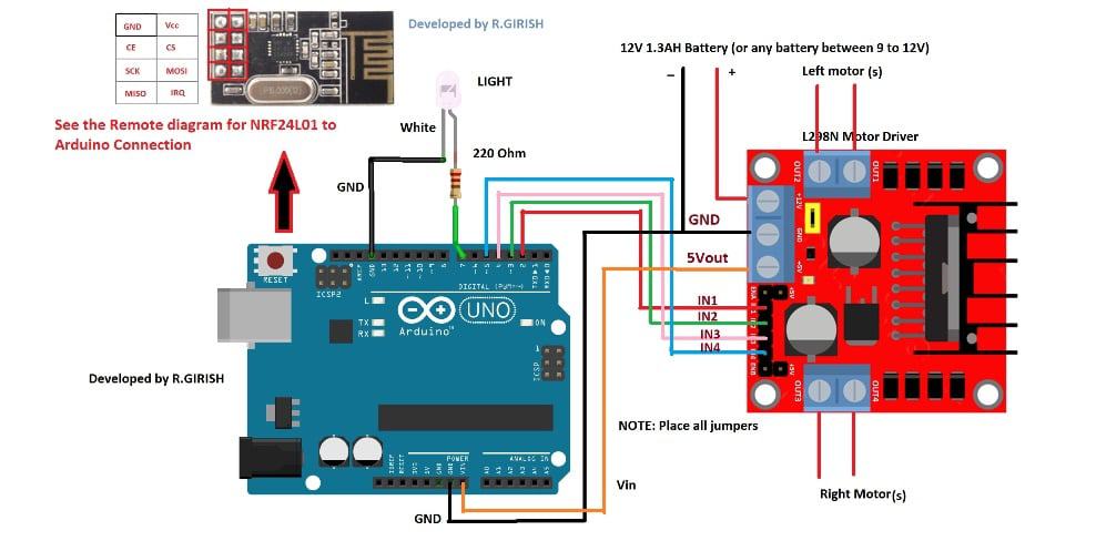
Please note that connection between Arduino board and NRF24L01 are NOT shown in the above diagram for avoiding wiring confusion. Please refer the remote’s schematic.
The Arduino board will be powered by L298N module; it has built in 5V regulator.
The white LED may be placed as head light or you can customize this pin to your needs, by pressing the joystick, the pin #7 turns high and pressing the joystick again will turns the pin low.
Please pay attention to the left and right side motors specified in the receiver schematic diagram.
Program for the Receiver
#include <nRF24L01.h>
#include <RF24.h>
#include <SPI.h>

RF24 radio(9, 10);
const byte address[6] = "00001";

unsigned long lastPacket = 0;
unsigned long timeout = 500; // ms

// motor pins
const int M1A = 2;
const int M1B = 3;
const int M2A = 4;
const int M2B = 5;
const int lightPin = 7;

struct Payload {
  int xVal;
  int yVal;
  bool light;
};

Payload data;

// helper functions
void stopMotors() {
  digitalWrite(M1A, LOW);
  digitalWrite(M1B, LOW);
  digitalWrite(M2A, LOW);
  digitalWrite(M2B, LOW);
}

void forward() {
  digitalWrite(M1A, HIGH);
  digitalWrite(M1B, LOW);
  digitalWrite(M2A, HIGH);
  digitalWrite(M2B, LOW);
}

void reverse() {
  digitalWrite(M1A, LOW);
  digitalWrite(M1B, HIGH);
  digitalWrite(M2A, LOW);
  digitalWrite(M2B, HIGH);
}

void leftTurn() {
  digitalWrite(M1A, LOW);
  digitalWrite(M1B, LOW);
  digitalWrite(M2A, HIGH);
  digitalWrite(M2B, LOW);
}

void rightTurn() {
  digitalWrite(M1A, HIGH);
  digitalWrite(M1B, LOW);
  digitalWrite(M2A, LOW);
  digitalWrite(M2B, LOW);
}

void setup() {
  Serial.begin(9600);

  pinMode(M1A, OUTPUT);
  pinMode(M1B, OUTPUT);
  pinMode(M2A, OUTPUT);
  pinMode(M2B, OUTPUT);
  pinMode(lightPin, OUTPUT);

  stopMotors();
  digitalWrite(lightPin, LOW);

  radio.begin();
  radio.openReadingPipe(0, address);
  radio.setChannel(100);
  radio.setPALevel(RF24_PA_LOW);
  radio.setDataRate(RF24_250KBPS);
  radio.startListening();
}

void loop() {

  // receive data
  if (radio.available()) {
    radio.read(&data, sizeof(data));
    lastPacket = millis();
  }

  // failsafe
  if (millis() - lastPacket > timeout) {
    stopMotors();
    return;
  }

  // joystick interpretation
  int x = data.xVal;
  int y = data.yVal;

  int center = 512;
  int deadzone = 40;

  // Light toggle
  digitalWrite(lightPin, data.light);

  // direction logic
  if (y < center - deadzone) {
    forward();
  }
  else if (y > center + deadzone) {
    reverse();
  }
  else if (x < center - deadzone) {
    leftTurn();
  }
  else if (x > center + deadzone) {
    rightTurn();
  }
  else {
    stopMotors();
  }
}
That concludes the receiver.
After completing the project, if the car moves in the wrong direction just reverse the polarity motor.
If your base car is 4 motors wheel drive, connect the left motors in parallel with same polarity, do the same for right side motors and connect to the L298N driver.
If you have any question regarding this joystick controlled 2.4 GHz RC car using Arduino, feel free to express in the comment section, you may receive a quick reply.


Questions & Answers
sir,how can we make a robot vehicle which will be able to track RF signal sources?..would you mind helping us in this situation..
Joydip, do you mean to say a RF remote controlled robot? sorry i did not understand what you meant by “track RF signal source”…explain elaborately