In this post I have explained a simple 48V inverter circuit which may be rated at as high as 2 KVA. The entire design is configured around a single IC 4047 and a few power transistors.
Technical Specifications
I am a big fan of u....i am a wisp. i need an inverter design with 48volt DC input and 230volt output supply and output power in the range up to 500w.
This inverter will be running 24*7*365 days continuously and should not have charging facility. will u please design the circuit and transformer running on 48v.
Thanks & Regards
Circuit Diagram
Circuit Description
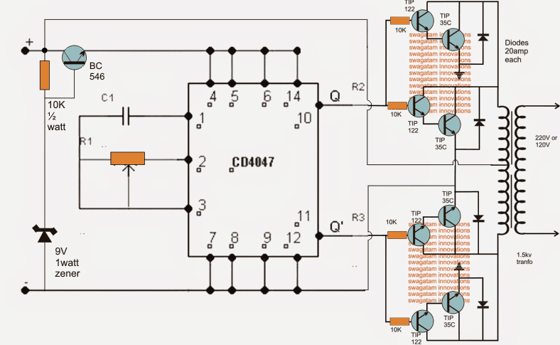
Referring to the shown 48V inverter circuit, the IC 4047 forms the main oscillator stage responsible of producing a totem pole outputs for the connected output stage.
The output stage is made by configuring a 4 individual high gain high power transistors modules, two of them on each channel of the push pull output stage.
The TIP122 are themselves internally configured as Darlingtons which are further attached with TIP35 transistor in the Darlington for generating exceptionally powerful current gain across each of the modules.
Setting up the Oscillator Frequency
C1 and R1 must be appropriately set for achieving the desired frequency as per the required specifications...could be 50 Hz or 60 Hz.
The shown 48 V inverter configuration is designed to generate a massive 2 kva of output power provided the devices are mounted on sufficiently large heatsinks and the battery rated at 48 V, 100 AH, also the transformer rated at 36-0-36V, 1 kva
For lower outputs, one of the modules could be eliminated from each of the channels.
The BJT BC546 is positioned to provide a reasonably fixed 9 V to the IC in order to keep the IC safe from the high battery voltage and within its specified working voltage limit.
Using Zener Diode to Drop Regulate the IC supply Voltage
In the above explained 48V inverter circuit I have used a BC546 emitter-follower series pass circuit to step down the 48V DC to 9V DC for supplying the IC 4047.
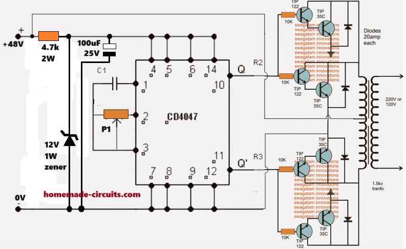
However, if the BC546 transistor is not available, we can incorporate a zener/resistor based regulator for achieving the same results, as shown in the following diagram:



Questions & Answers
Hello Sir!! I am a 4th year B.Tech Student Electrical Eng.
We are trying to make pure wave sine wave inverter using PWM and bubba oscilator for our Final project.also along with it a battery charging and auto cut off circuit would be needed
We want the inverter to work for day to day purposes.We would be grateful to you if u can give a working circuit fr this.
thnk u!
Hello Ritwik please specify the following:
battery voltage?
inverter wattage?
battery voltage would be around 24 V
Wattage 500W
Is this inverter specification alright fr thr project demonstration??
or should go with a smaller wattage say 100W
Inverters can be made right from 10 watts to 100000 watts regardless of their types,
watts and volts are not specific to inverter designs….so 24V 500 watt is just one of the ranges and can be incorporated for your application.
100 watt would be better since it would require smaller parts.
I'll try to post it soon…keep in touch.
hello sir …
CS9012 Transistor is same BC 557 (PNP).and CS9013 Transistor is same BC547????????
(9012 = 557)
(9013 = 547)
9012/9013 = 500mA, 30V
BC547/557 = 100mA, 45V
Ok sir 100W inverter would do then…
thnk u
Please try to post soon 🙂
OK!
Dear Sir,
Please upload a very very simple inverter circuit by which I can run a 100 W A.C fan only.
It's input should be 12 V.
Thanks in advance.
Regards.
Rashid R. Ansari
Dear Rashid, you can try the following circuit
https://www.homemade-circuits.com/2012/02/how-to-make-simplest-inverter-circuit.html
Sir..
I am unable to find those transistors (9012,9013) . So
can i use 547, 557.
((This is the curcuit of firealarm using electronic buzzer alarm .))
you can try 2N2222, 2N2907 instead
BC547/557 are 100 mA rated, not sure whether it'll work for your application or not.
Can i use a 12v input
yes, can be used
ok all I would have to do is apply 12v, nothing wouldnt have to be changed other than adding a 12-0-12 transformer
that's right….the BC546 will not be required with a 12V battery as the supply
ok all I would have to do is apply 12v, nothing wouldnt have to be changed other than adding a 12-0-12 transformer
can I use something else instead of the 20amp diodes could I use resistors if so what values could I use, only 3amp diodes are available where I am.
20amp diodes would be necessary if the trafo is also rated at 20+ amps…for smaller trafos the diode ratings may be appropriately lowered
…resistors cannot be used instead of diodes for freewheeling application
Just asking something that I was in a discussion with a friend about, he says negative and positive voltage in relative is actually the samething it's just the direction of flow that makes the difference, would you say that's true? If not could you explain what the actual difference is.
yes that's correct…
So what if I have a DC fan that uses a positive 12 volt but I have a source that is negative 12v could I apply the 12volts to a regulator and connect the fan to the out put and get it to work?
If yes then I would assume that I have to use a positive voltage regulator to do so and if that's the case why wouldn't I get the same results if I used a negative voltage regulator since I would be directing the flow of current by using the regulator.
if you have a -12V supply, you would also have the other wire as the +12V….use this other wire as the (+) for the motor…
What's the value for the pot and and the c to get 50hz and ho do you calculate it
you can try a 22k pot
value of c
1uF/25V
If its electrolytic would that be a problem because I am wondering if thats the problem on my 4047 inverter…. I can only get that value as polarized so dont know which way to turn it.
you can use two nonpolar 0.47uF capacitors in parallel, or simply first try with a single 0.47uF for getting the required 50Hz frequency
ok then will build this tomorrow and I will use 12v, I wont use the bc546 do I need the 10k 1/2 watt resistor?
the 10k resistor, zener and the BC546 can be eliminated if a 12V supply is used.
ok i just built it I could only find code 473 resistor and I used some tip3055 along with 3 tip106 and 1 tip105 and I only had a 50k pot I used 1 amp diodes accross the transistors and used a half amp transformer at 12v just to test but I got no output.
check if the output is oscillating or not, and also check your battery current and voltage.
I am getting 5 amps on the positive leg of the battery and 2amps on the negative leg, 0v ac from transformer, battery voltage wen circuit is attached is 12.30v and detached it is 12.67v, I got 33khz from transformer, transistors seems normally warm nothing too much but the transformer get hot i think because of high frequency.
I got 5v across the output pins 10&11 of ic 4047
also I am getting 10v dc between center top and each end of the input of the transformer.
make the frequency 50Hz and then check…
and different current readings on +/- poles of the battery is not possible, how did you check it?
also without any load the amp reading should be very small, in milliAmps
i used a clamp meter to check amp readings, and which capacitor can I use to get 50hz
put an ammeter in series with the positive line to get a physical reading of the consumption
would a 0.02mf get 50hz
verify it with a frequency meter or refer t the formulas presented in this article:
https://www.homemade-circuits.com/2013/09/ic-4047-datasheet-pinouts-application.html
C will be in Farads
I dont know what that means :1/8.8RC at pin10 and 11 which would be the way to work out the frequency at 50hz.
use a frequency meter then…
I have a multimeter thats all, I just wanted to know which capacitor to use, I tried a code 104 on a basic setup of a 4047 inverter and I adjusted the 50k preset I used and I got it to 100hz, I just need 50hz
how do you know it's 100Hz?
try two 104 in parallel
my multimeter can do frequency test, i just put both probs onto the output of the transformer and adjust pot and thats the lowest it went, about 119hz
if you had a frequency measuring facility then why were you not using it so far?
anyway increase the capacitor and check again… these are so basic stuffs…
Each time I made a test I told you the frequency so why would you assume I didnt have a device to test even after I told you that I had one….. there are alot of capacitors, it would take very long to go through all just to get one frequency I am not a pro…. anyway I got the 50hz, thanks anyway.
I used irfz44n I didnt use any driver transistors and then power transistors I used 100ohm resistors to feed the gates to increase power I can just bridge from those same 100ohm resistors to gates of additional fets or should I add more 100ohm resistors?
If you have a proper frequency meter then it's just a matter of adjusting the relevant preset or capacitor and measuring the results, that doesn't require to be a pro.
yes your fet connections are OK. you must add separate resistors for each parallel fet.
Good Evening Engr. Swagatam! ^_^
Can you describe the uses briefly? :
1. 4 x 10k resistor
2. 4 x diodes (except zener)
tnx for the info…I need it for our interview…in which I chose this type of circuit…
Eshkariel, the 4 resistors are for biasing the respective transistors so that they can conduct and induce the oscillating current in the trafo.
the diodes are for safeguarding the transistors from the reverse EMFs from the trafo winding during their OFF periods
What a speedy reply!! Tnx engr.! ^^
you are welcome!
Can you explain the use of zener diode as a shunt regulator??.
And the BC546 too…..how does it regulate 9v for the IC?….R
The input voltage from the collector of BC546 is 48v right?…
Tnx.. 🙂
🙂 it is not a shunt, it's an emitter follower, please Google how an emitter follower works.
yes collector is 48V, but the emitter will be slightly less than the base zener value…8.4V to be precise
I was thinking about something I dont know if it could happen can I actually parallel 2 or more boost converter outputs together?
It's possible, but doesn't make sense
I'll give my reason for wanting to try it, but first why wouldn't it make sense?
outputs are normally connected in parallel to increase current, but for a boost or buck converter it can be simply done by modifying the coil and the power device.
OK then I assumed that… The idea behind using a boost converter is for an inverter purpose, I'm assuming also you will say that using a boost converter is pointless or inefficient. I wanted to use it because it would then allow me to buy smaller transformers for example if I wanted to build a 2000 Watt inverter I would need to pull atleast 166 watts from my battery bank also the primary of the transformer would need to be able to manage that amount of current also and that's impractical for a transformer fitting into a regular size inverter enclosure, but if I had a boost converter which I could use an inductor which could manage the 2000 watts but with an output of 60-100v then it would be much simpler to buy or build a transformer of that spec and also it would be smaller and more suitable, if that makes sence to you then let me know…. If so could you design a boost converter to step up a 12dc to 60v or above at high enough wattage 2000 and above
No it doesn't make any sense at all, it's like trying to make a car engine by joining 4, 5 motorcycle engines….for your own satisfaction you can surely try it out and see how it performs
instead of using a boost converter it's better to use many 12V batteries in series
what if I dont have many 12v batteries to connect in series for example I just have 2 that would mean the transformer will be huge to manage over 160amps for something like a 2000watt inverter but for example if I have (2) 225ah 12v batteries and I want to parallel them but I need a 2000 watts which I would need 166amps and that transformer couldnt hold in a small case but if I had a boost converter to boost the voltage up to say 60v from 12v then I could use a much smaller transformer thats the point I am trying to make, I still dont know if that makes an sense to you.
An inverter is itself a boost converter, so there's no need of involving two transformers for the results….you can use the concept which is discussed here and which you have already studied
https://www.homemade-circuits.com/2014/07/5kva-ferrite-core-inverter-circuit.html
HI Mr. SWAGATAM MAJUMDAR
I hope you will fine and enjoying a good life.
I am your web student, this is a big honor for me. I am thankful to you because I have made many project of your design and published that with your name.
Now I want to make a 48v or 96v 500Watts inverter to reduce load current for a ling battery backup.
Will you help me to make this?
1 The above diagram is used for 48v inverter or there is some change in it.
2 The Transformer is used in this diagram is 36-0-36 or 48-0-48 volt.
Thanks
Regard : Engineer Hafiz Abdul Wahab Mirza
Thank you Mr. Hafiz,
you can use the above diagram exactly as shown, with a 48V/56V supply.
the transformer can be 42-0-42 or 45-0-45V but not less than this.
the output will be an ordinary square wave.
my wimax poe adapter is short…pls help me
This is a totem pole design is it the norm across pin 10 and 11 to be 100 or 120hz?
for 50 Hz, it will be 100Hz and for 60Hz it will be 120Hz
if I need 50hz or 60hz operation? I ask because I want to build a complete inverter circuit with the arduino so I am trying to work up all the details I seem to forget
yes it will be as stated in the previous comment….
the output from one wave form should be inverted or should both wave forms be normal? from pins 10 and 11?
both will be same (positive)…..the alternate inversion is done by the transformer
can this circuit be modified to gain 30khz?
I am not sure about it, you can check the datasheet of the IC to confirm it.
I cannot understand that schematic, I don't see frequency at any point on it
hi Lynch
the frequency is set with C1 and R1.
with a fixed capacitor at C1 and a variable resistor at R1, R1 can be adjusted to get the desired output frequency at pin 10 and 11
good day sir thanks for the post i have learnt from it but sir i stil find a problem in determining the gauge of wire that i need to use for winding both primary and secondary part of the transformer so help me pleasr
OLupot, you are not supposed to wind the transformer at home, i wouldn't recommend that, instead you must buy it readymade or get it built by a professional trafo designer.
ok now i get you better i will buy one from a transfo proffessional
You can determine the gauge of wire to be used by calculating the current from VA/Vpri, then do Current/current density(between 2.2 and 2.4 for copper) to get the conductor size. After getting the conductor size, you can relate it with the AWG standard. Problem solved. ?
I want to know how you arrived at 2kw power from the transistor connection. Thanks
each TIP35 is rated to handle 25 amps and two of them are connected in parallel on each channel, and the battery voltage is 48V, therefore multiplying, 25 x 2 x 48 gives 2400 watts…I hope you have understood now…
…..buy what about the maximum collector power dissipation Whuch is 90W. Does it not have effect at all?
you must consider the calculation after a heatsink is connected, not without a heatsink.
Can I also ask if it’s a pure sine wave or square wave. Although, I thought its a pure sine wave until I saw a comment that it’s square wave inverter, pls send more light. Thanks
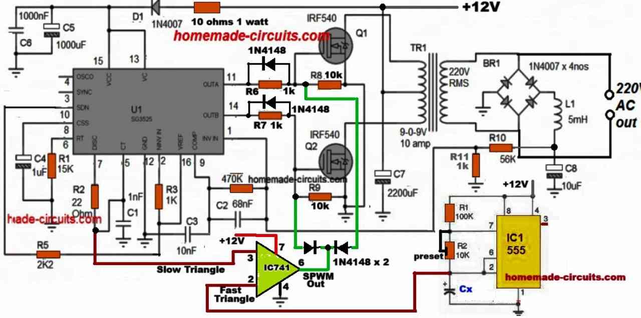
How can it be a sinewave? there’s no PWM attached here…so it is a square wave design
It can be a sine wave because CD4047 can be used to produce a pure sine wave inverter. What do you mean by “no pwm attached to it”?… I want to learn pls
here only a simple 4047 inverter is shown so it cannot be a sinewave, a sinewave example can be seen here:
https://www.homemade-circuits.com/pure-sine-wave-inverter-circuit-using/
I am still not cleared on Something. TIP35 has a maximum collector power dissipation of 90W from its data sheet but from your calculations above, one TIP35 would handle 1200W for 48V which looks contradicting. Pls shed more light.
Also, what is the function of TIP122 at the power stage. Pls, I need responses
It is not 90, it is 125 watts…that is power dissipation rating at 25 degree Celsius.
According to my analysis, this refers to the maximum wattage the device can handle without an heatsink.
But the datasheet also mentions that the device can handle 100V at 25 amps across its collector/emitter, which is beyond the capacity of the device without a heatsink, therefore a large heatsink must be attached to enable normal working of the device…
The TIP122 is added to create a Darlington pair with TIP35 because the input from the IC can be too low to operate the TIP35 directly, you can use any other power device such TIP31 etc…
Wil BC546 still work for a 96-0-96 transformer for higher watt say 10kVA?
And what if I wanna include a charger facility using a relay, can you pls help me out?
for 96V you may need to replace it with MJE340 BJT…..once you finish building finish the inverter then we can discuss the relay changeover section elaborately
Okay. Thanks. You’re such a blessing. Will get back to you
Pls,im waiting for responses oo
For 1kw inverter what tytransformer is used (ratings and type)?
divide 1000 with the respective voltage ratings of the transformer winding, you will get the approximate ratings for the winding…it will iron core type, center tap.
Can u give the rating (12-0-12 or 18-0-18)for 1kw inverter
divide 1000 by 12, and 1000 by 24 for the primary current rating respectively…similarly divide 1000 with 220 for getting the secondary current rating
Good day Mr Swagatam, we ar appreciative of what u ar doing for human raise. Pls can u show me d diagram of how to connect a relay on inverter so dat when light frm d grid comes it wil be charging automatically. God bles u.
Good day Yusuf,
you can try the last diagram from the following article
https://www.homemade-circuits.com/how-to-convert-inverter-to-ups/
I used CD 4047IC,got 6VAC on pins 10& 11 ,fed it to IRF540 mosfets it drastically drops to around 2VAC and I need 12VAC to be stepped up. What can I do to get 12VAC?