In this article I have explained a 32V, 3 amp SMPS circuit which may be specifically used as an SMPS 100 watt LED driver, rated with the same specs.
The circuit of the proposed 32 V, 3 amp smps led driver may be understood with the the help of the following points:
Circuit Operation
The mains voltage is rectified and filtered by the bridge network and the associated filter capacitor C1. This rectified 310 V DC passes through R1, R2 and triggers T1 into conduction.
T1 switches ON and pulls this DC to ground through the 30 + 30 primary winding inducing a steep pulse through this winding and also across the lower auxiliary winding.
This pulse across the auxiliary winding enables a negative pulse to be generated at the junction of R1/R2 which momentarily sinks the base drive to ground such that T1 now shuts off.
In the meantime C2 charges up drying up the auxiliary winding impact, and allows T1 with a fresh triggering potential at its base.
T1 conducts yet again and the cycle keeps repeating at a frequency determined by the value of R2/R3/C2 which could be around 60 kHz here.
This rapid switching induces a corresponding voltage and current across the secondary winding which may be well over 32 V, 3amps AC as per the given winding details.
The above voltage is appropriately filtered by C4 and applied across R6, R7 for feeding the shunt regulator and the opto coupler stage.
R6 is appropriately adjusted such that the output voltage settles to about 32 V.
The Shunt Regulator
The shunt regulator instantly activates the opto in case the voltage tends to rise above the set value.
The opto in turn "kills" the base drive of T1 temporarily disabling the primary operations until the output potential is restored to the correct value, the opto now releases T1 and allows the operations to work normally, only until the output rises again to initiate the opto yet again, the process keeps repeating ensuring a constant 32 V at the output, for driving the 100 watt LED module safely
Circuit Diagram of 32V 3A LED Driver for 100 Watt LED
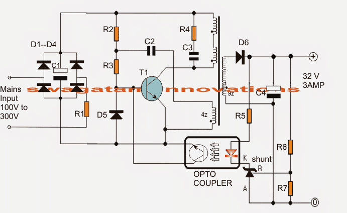
The transformer is wound over a standard EE ferrite core having a central cross sectional area of at least 7 square mm.
Referring to the figure, the upper two primary winding are made up 30 turns of 0.3 mm diameter super enameled copper wire.
How to Wind the Ferrite Transformer
The lower primary auxiliary primary winding consists of 4 turns of the same wire as above.
The secondary is wound with 22 turns of 0.6mm super enameled copper wire.
The procedures are as follows:
- First begin winding the upper 30 turns, secure its ends on the bobbin leads by soldering, and put a thick layer of insulation tape over these turns.
- Next, wind the secondary 22 turns and solder its end terminals on the other side of the bobbin leads, put a layer of thick insulation tape.
- Over the above layer start winding the auxiliary 4 turns and as above secure the ends appropriately on the primary side leads of the bobbin, again put some layers of insulation over this,
- Finally, wind the second 30 primary turns starting from the previous 30 turn end, and secure the end over one of the leads of the bobbin on the primary side.
- Cover the finished winding with additional layers of insulation tapes.
- Make sure you remember the terminated leads properly so that you don't make incorrect connections with the circuit and cause a possible fire hazard.
Parts List
All 1 watt, CFR
- R1 = 10E
- R2 = 1M
- R3 = 470E
- R4 = 100E
All 1/4 watt MFR 5%
- R5 = 470E
- R6 = preset 22k
- R7 = 2k2
- C1 = 10uF/400V
- C2 = 2.2nF/250V
- C3 = 220pF/1kV
- C4 = 2200uF/50V
- D1---D4 = 1N4007
- D5, D6 = BA159
- shunt regulator = TL431
- opto = 4n35
- T1 = MJE13005
Useful Feedback from Mr. Kanicaras about the above circuit
Well, I tried experimenting with transformer, and doing so, I found quite a few things about the circuit:
First of all (unfortunately), this circuit is inappropriate as power source for the power supply, because the transistor blows, when circuit is not loaded (or is loaded too little).
It works well only with the load (such as 100W LED) connected to it all the time. Learned it the hard way – blew three transistors. I think that TL 431 is the culprit here. It is rated only 37V Cathode to Anode voltage.
When circuit is unloaded, it struggles to regulate the voltage at 32V (very near its own brake down voltage) and after 30 seconds or so it stops regulating (maybe because of the sporadical pulse larger than 37V) and the voltage goes up through the roof, taking down the transistor (I think through the feedback coil, because of the sharp voltage increase in it).
Secondly, I think that there are too many turns in secondary coil. 22 turns can give more than 70V unloaded (saw this number after loss of regulation, just before transistors blew) I think, that 15 or even 10 turns would be enough for 32V at the output (winding 2 or more wires in parallel).
By the way, increasing C2 capacitor value to 10 nF or more, decreases the frequency of the oscillation to human audible range (~14 kHz, checked on oscilloscope and also faintly herd it). So, I guess, its not such a good thing after all ;).
The ferrite core, that I got, came from a very old ATX so I'm not sure that it is "standard"
I found another bigger transformer. I'm going to disassemble it and try to use it in this power supply
I'll certainly try parallel strand "tactics".
Besides that, I'm going to buy some parts (including 220 pF capacitor and 4n35 opto), because, interestingly, I "fried" R5 resistor by accidently shorting the output of the power supply (while trying to connect the small light bulb :).
The lead welded itself to the light bulb and in 1 or 2 seconds (that's how long it took to disconnect it) R5 went up in smoke.
I guess that's one of the disadvantages of this power supply – you cannot short it under any circumstances. I imagine what it would be like if it was not 4 W (in my case) but fully functional power supply at 100 W.
Before I "fried" R5 resistor I tried this power supply with 120V AC input (I have DIY 100W 220V/220v/110V isolation transformer) and it gave less voltage and power than with 220V. Is that normal (is this power supply calculated only for 220V mains)?
Potential Improvements
I didn't give up on this circuit, and it paid off I replaced the shunt regulator – the circuit worked a little bit better (gave a bit more power).
But the most important change occurred, when I decided to change C2 capacitor (its value in my prototype circuit was a bit off ~1.99 nF).
When I put 2.2 nF capacitor in, the power output grew a bit more. Then I decided to increase it again and when I reached 10 nF the output was reaching ~40W (20V at ~2A and that's with my very first small transformer).
The second thing that happened (after I increased C2 value) was, that transistor started heating up quite rapidly (in my prototype board I didn't attach the heat sink to it yet, I just switch it on for a short periods of time).
I think, that this shows, that there is something wrong with the parameters of the transformer itself (maybe, that's why adapting the circuit to the transformer helped?)
I don't really know, if it's the right way to go though.


Questions & Answers
Sir i don't understand assemble transformer! if there is youtube video? or can get this in shop transformer. please guide me regarding this assmbly.
Ashok, take a suitable E core bobbin and start winding as per the given instructions in the article, it's not so difficult,
if possible I'll try to update the steps through diagrams soon.
hey Swagatam, you sure you got the resistors right in the explanation of the circuit? I think you wanted to mention R2&R3 whereas R1 is gotten into mix ?
thanks Bart for pointing it out, I'll correct it soon…
Sir i built this project. but i have a problem with T1 it's generate over heat although i but heat think but it's still over heating
Mahmoud, did you wind the transformer correctly? Make sure to add a paper gap between the surfaces where the two Ecores touch each other.
also the winding should be tight and cleanly wound
you may also try increasing the number of turns to 50 instead of 30.
sir have you the PCB design
I don't have it, a PCB maker will design it for you
dear, is there any substitute to e-core, such as ferrite rod or nut bolt type
dear dinesh, an Ecore is the most efficient option, any other substitute will make the design bulky and inefficient.
who to modify this circuit to drive 32 watt led
what is the voltage and current rating of the LED??
i am using 500 leds of 3.2v 20m
if your LEDs are 20mA type then I thing you can try a simple capacitive power supply,
if you are interested to operate them with the above circuit then you can do it by making 50 strings of LEDs with each string consisting of 10 Leds, now connect all these strings in parallel, next connect the positive common end of the assembly to the positive of the supply and negative to the negative of the supply.
Thank you sir
one more question sir,
if i am using simple capacitive power supply, how to calculate resistor value (formula) that should be connected in parallel to capacitor with same set of leds.
Thank you
Hi Shekhar, the parallel resistor is only for discharging the cap while the circuit is being unplugged, so the value is not crucial, you can use any value between 330k to 1M
Hello Sir,
can you design a driver circuit to operate a spare lcd of a laptop… so that it can be connected to a db 15 pin connector.
Thank you
hello Shekhar, the driver circuit may be already there in this blog, but I am not sure about the 15 pin connector and its wiring details,
thank you sir
i tried but i didn't find that… can u give me the link
you can try the following design:
https://www.homemade-circuits.com/how-to-design-simple-led-driver-circuits/
Hello sir,
I have build this circuit using quite a few different components (because I didn't have needed ones at hand). First of all, the ferrite transformer core was "E" (dimensions of the central area (where the bobbin goes) were 9.8 mm x13 mm, I don't know if it is adequate for 100W) and "I" type with plastic sheet in 0.3mm gap (I took it from ATX power supply). Windings were as follows: 30 turns of 0.4 mm diameter wire, 20 turns of 0.65 mm diameter wire (couldn't fit more in one layer), 4 turns of 0.4 mm diameter wire (spaced to cover all of the aria of the bobbin) and 30 turns of 0.4 mm diameter wire (connected to the first 30 turns). The components that I changed in the schematic are: TLP371 optocoupler (instead of 4n35), BYV29-500 diode (instead of BA159 (D6)) and C3 was 280 pF 1kV (I had 2 470pF 1kV capacitors, connected them in series –> somehow got 280 instead of 235 pF???).
In this configuration, power supply gives ~20V (with 120 ohm 5W load resistor connected to it). The problem is, that I can't get any significant current out of it (I connected 2 20W halogen lamps (connected in series) to it and the voltage dropped to 2.5 V).
Can You tell me, where the problem with my power supply is?
Hello kanicaras,
the ferrite inductor should be compact, meaning there should not be a too much free space between the coil and the side E cores.
I would like to know how much voltage you are getting at the output without connecting any load?
for increasing current use parallel strands of wires for winding the secondary, instead of using a single thick wire, more number of strands will ensure more proportionate amount of current.
R6 can be tweaked for adjusting the output current as per the load preference.
Hello,
After winding the transformer it is quite compact (I tried to make it as compact and neat as I could), there is not much space left for additional windings (maybe for 1 layer of 0.65 mm wire with the layer of insulation –> there is only ~1.5mm gap (from each side) between the outside of the core and existing windings).
I also mentioned, that my transformer core consists of "E" and "I" parts (not two "E" parts). Could it be the cause of the problem?
I measured the voltage without the load – it was 27.9V and it could be adjusted with R6 potentiometer (it is interesting, that, with the load connected, R6 does nothing).
By connecting different loads I calculated the power coming out of my supply and it was only ~4W (in regular 50Hz transformer 0.65 mm wire should at least give 0.7A at ~ 28 V = ~20W, in SMPS it should be capable of much more than that) :).
I looked at the output (before rectifying diode D6) on the oscilloscope –> without the load there is big oscillation in output signal (looks like some odd combination of square and sine wave). However, when the load (5W 120 ohm resistor) is connected, the signal resembles square wave, but there is a huge (-100V) negative spike before each cycle of oscillation. I don't know, if it normal or not.
electrically and magnetically E/I and EE are identical with their strengths, so according to me that cannot be the issue. the winding have polarity, so you could check that….check without connecting anything across the secondary of the trafo with an ammeter in the AC range, connect the prods directly across the secondary winding and see how much current it reads
by the way I hope you've followed the exact instructions that's been furnished in the above article.
Hello,
I read somewhere, that the low output power issue could be associated with ferrite core permeability (which, namely for my core, I don't know). It is possible, that I will have to rewind the transformer several times before I find the right winding ratio for this power supply "driver".
Of course, first I will triple check if my schematic is correct and all of the components are funcional (I'm not particularly happy with that negative spike at the output of the transformer).
For the direct measurement of the output current, I cannot do it for now, because, currently, I haven't got the multimeter that could measure current higher than 400 mA.
it could be, but today all ferrite cores are made with standard features and characteristics, so it cannot be so crucial.
I hope you have used many strands of wire together in parallel in the secondary winding for optimizing current rating
Hello,
The ferrite core, that I got, came from a very old ATX so I'm not sure that it is "standard" 🙂
I found another bigger transformer. I'm going to disassemble it and try to use it in this power supply 🙂 I'll certainly try parallel strand "tactics".
Besides that, I'm going to buy some parts (including 220 pF capacitor and 4n35 opto), because, interestingly, I "fried" R5 resistor by accidently shorting the output of the power supply (while trying to connect the small light bulb :). The lead welded itself to the light bulb and in 1 or 2 seconds (that's how long it took to disconnect it) R5 went up in smoke.
I guess that's one of the disadvantages of this power supply – you cannot short it under any circumstances. I imagine what it would be like if it was not 4 W (in my case) but fully functional power supply at 100 W.
Before I "fried" R5 resistor I tried this power supply with 120V AC input (I have DIY 100W 220V/220v/110V isolation transformer) and it gave less voltage and power than with 220V. Is that normal (is this power supply calculated only for 220V mains)?
Hello, if it's from an ATX then it should be extremely standard.
R5 can never fry under any circumstances, because the entire configuration across the output winding it specifically positioned for tackling overload and short circuit conditions.
It might burn only if the opto fails to short the T1 base to ground…recheck and confirm the opto connections properly.
the circuit is designed to work right from 85V to 285V…so 120V can never be an issue.
I'm almost at the point of giving up 🙁
I bought and replaced the parts (220 pF capacitor and 4n35 opto). With the first transformer it worked the same as before (again only 4 W).
Triple checked the schematics –> it's good. I also made breadboard version of it for easy component replacement (it worked the same as the one on prototyping board).
Dismantled SMPS transformer from 250W computer power supply (E+E type with spacious bobbin) and wound quite few combinations of turns from 2×25 turns (when it stops working at all) to 2×50 turns of primary winding (using the same 0.4 mm wire). Although I kept the ratio of secondary/feedback/primary the same. Also I tried to use parallel winding for secondary (used 4x 0.4 mm wires), with no success (again the same 4W).
May be, the output of this power supply is very sensitive to transformer winding ratio or transformer construction specifics (gap between core parts, wire diameter and so on, for example, dismantling the 250W transformer, I saw that manufacturer used copper plates as high amperage winding).
the above circuit was actually tested and confirmed by the original creator of the circuit as per its mentioned ratings, so as far as the design is concerned, it's perfect.
You might feel that you have done everything right in your prototype but still there could be something missing or hidden which might be preventing the circuit from functioning optimally.
Please note that the only the black dots indicate the joints, while the lines which cross each other without the dots are not connected.
yes the primary oscillation is strictly depended on the primary winding specs, so the the winding of the trafo is critical.
you can try this:
isolate the secondary winding completely from the associated circuitry and first confirm with a voltage and the amp levels from the trafo directly.
put the meter in the DC range and check the voltage, the reading would indicate approx 50% of the actual value present, next you can connect the meter (in the DC Amp range) and check the max amp that's being put out from the winding directly…these will confirm the actual status of the circuit.
Hello,
Disconnected the secondary from the circuit and, when I powered my power supply on, the circuit (or rather, the transistor in it) was shorted immediately.
Then I repaired the circuit, connected the secondary winding back to the rest of the circuit and took out the opto. The schematic started working, giving about 38V (with 120 ohm, 5W load –> didn't want to damage 50V electrolytic), but no power again (this time it was ~5 or 6W).
Does shorting out (with disconnected secondary) mean something is wrong with my power supply???
according to me disconnecting the secondary shouldn't have affected the primary, unless the leads were shorted, so I think it indicates some thing may be unbalanced.
By the way you can switch to the following circuit if you are having difficulty with this one…the following circuit is an IC based so the winding data is not too critical here:
https://www.homemade-circuits.com/2014/06/smps-2-x-50v-350w-circuit-for-audio.html
Hello,
I was thinking about something like that, but it's not regulated and, from the looks of it, also would need specially wound transformer (especially, because of the lack of voltage control on the output) :(.
The thing is, that I want to use it as power source (instead of heavy mains transformer) for my adjustable linear power supply (which I already constructed and don't want to burn in case of overvoltage coming from the SMPS).
This very simple power source, with voltage control (if I somehow managed to make it work) was just the thing.
I was also looking at circuits based on TL494 but they are quite complex (and most of them are built for a specific purpose and doesn't fit my requirements).
Hello,
voltage control is not an issue, the entire opto-coupler stage as given in the above design can be integrated in this design also…the opto transistor can be attached with the pin3 and ground of the IC for the required actions,
and the transformer is nothing special, it just needs to be wound as per the given data.
you need a simple power source at 3 amp current or at any lower level? I thought you are making it specifically for driving a 100 watt LED lamp which requires a 3 amp current input
Hello,
I am constructing 30V 3A linear adjustable power supply (that's why I was interested in this circuit). This circuit would be very compact, easy to construct ;), gives needed power 32V (additional 2 V are needed for the drop at the power transistor) at 3A and, also, cheap.
Well…I will try building power source based on IR2153 and cross my fingers for it to work (because, this time, it won't be easy to build :).
Yes the above circuit is good but since you are having difficulties optimizing it I referred you the other one, where the frequency is not transformer dependent.
since in the referred circuit an IC based oscillator is used, this will be easier than the above as far as controlling its specification is concerned.
Hello,
I didn't give up on this circuit, and it paid off 🙂
I replaced the shunt regulator – the circuit worked a little bit better (gave a bit more power). But the most important change occurred, when I decided to change C2 capacitor (its value in my prototype circuit was a bit off ~1.99 nF). When I put 2.2 nF capacitor in, the power output grew a bit more. Then I decided to increase it again and when I reached 10 nF the output was reaching ~40W (20V at ~2A and that's with my very first small transformer). The second thing that happened (after I increased C2 value) was, that transistor started heating up quite rapidly (in my prototype board I didn't attach the heat sink to it yet, I just switch it on for a short periods of time).
I think, that this shows, that there is something wrong with the parameters of the transformer itself (maybe, that's why adapting the circuit to the transformer helped?)
I don't really know, if it's the right way to go though.
oh that's great, I am sure this info will help the other readers too, when they try this circuit.
Increasing the 2.2nF cap to 10nF has simply allowed the mosfet to conduct optimally or allowed it to reach the saturation point, which in turn has allowed sufficient current to pass through the winding.
yes it could be right, now the mosfet could be responding as per the winding of the trafo, but anyway now it looks better and should work as per the expectations.
Heatsink is a must and applying an heatsink won't be unnatural, so may go ahead and fit a good large finned type heatsink to safeguard the device…
Hello,
Well, I tried experimenting with transformer, and doing so, I found quite a few things about the circuit:
First of all (unfortunately), this circuit is inappropriate as power source for the power supply, because the transistor blows, when circuit is not loaded (or is loaded too little). It works well only with the load (such as 100W LED) connected to it all the time. Learned it the hard way – blew three transistors. I think that TL 431 is the culprit here. It is rated only 37V Cathode to Anode voltage. When circuit is unloaded, it struggles to regulate the voltage at 32V (very near its own brake down voltage) and after 30 seconds or so it stops regulating (maybe because of the sporadical pulse larger than 37V) and the voltage goes up through the roof, taking down the transistor (I think through the feedback coil, because of the sharp voltage increase in it).
Secondly, I think that there are too many turns in secondary coil. 22 turns can give more than 70V unloaded (saw this number after loss of regulation, just before transistors blew) 🙁 I think, that 15 or even 10 turns would be enough for 32V at the output (winding 2 or more wires in parallel).
By the way, increasing C2 capacitor value to 10 nF or more, decreases the frequency of the oscillation to human audible range (~14 kHz, checked on oscilloscope and also faintly herd it). So, I guess, its not such a good thing after all ;).
Thanks, I appreciate your efforts and the information that you have provided so far, all these will certainly help the viewers.
yes it makes sense, without load this circuit might have the tendency to go unstable and blow the transistor…because the mosfet oscillation is heavily relying on the primary coil loading which in turn is directly dependent on the secondary coil loading, so unless the secondary is loaded the primary side can get "rattled"
anyway thanks a lot for the info, if you happen to get a remedy for keeping the circuit stable without a load, do let us know:)
Hi Swagatam, Ajay Here. First of all, I want to appreciate for great work done by you. Very clear and descriptive design presented.
The circuit above given by you is for up-to 100W. I want to make such circuit for up-to 20W by keeping output Voltage 12 and 24V. Can you please make such circuit.
Thank you Ajay, you can easily tweak the output voltage by adjusting the value of R7, the current is not important as it will automatically settle down to the load's requirement once the voltage is matched with the load's specs
Hello, first thank you for the schematic circuit, I have a doubt, the ferrite core, the center must have 7 square mm (2.65 mm x 2.65 mm) or have to have 7 x 7 mm? I can use one of a generic ATX, or is bigger or smaller? Thank you very much, Nelson.
Hello, the rule of the thumb to find a core and bobbin which will comfortably accommodate all the winding and the specified number of turns….not too loose not too tight, smaller assemblies will make the winding crammed and prone to ferrite breakage while bigger assemblies will produce poor core response and conversions….
Hi Swagatam, Thanks for the schematic and the detailed instructions. By any chance do you have transformer winding instructions for Dummies ? 🙂 I've built electronic circuits in the past but never wound a transformer so not sure how to do it. I would really appreciate your guidance on this matter.
Hi Cesar, I am too not so good with transformer winding, I always leave it to the professional winder whenever I require one.
can i use a transformer from generic mobile charger. and assemle it as you shown in the circuit. ??
No that won't work, the transformer has to be precisely calculated and designed as suggested in the diagram.