Here we will study the design of a simple automatic mains AC voltage stabilizer which can be applied for safeguarding appliances like TV and refrigerators from fluctuating voltages.
A voltage stabilizer is a device which is designed to sense inappropriate voltage fluctuations in AC mains supply inputs, and correct them to produce a stabilized voltage for the connected appliances or gadgets.
Audio Video Representation
How the Circuit Functions
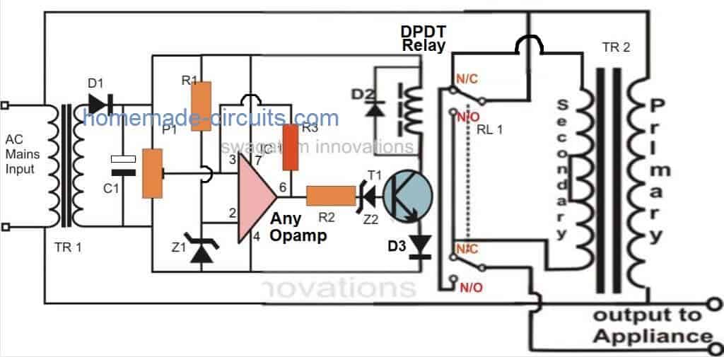
Referring to the figure we find that the proposed automatic voltage stabilizer circuit is configured with the single opamp IC 741. It becomes the control section of the whole design.The opamp is wired as a comparator, we all know how well this mode suits the IC 741 and other opamps. It's two inputs are suitable rigged for the said operations.
Pin #2 of the IC is clamped to a reference level, created by the resistor R1 and the zener diode, while pin #3 is applied with the sample voltage from the transformer or the supply source.
This voltage becomes the sensing voltage for the IC and is directly proportional to the varying AC input of our mains supply.
The preset is used to set the triggering point or the threshold point at which the voltage may be assumed to be dangerous or inappropriate. We will discuss this in the setting up procedure section.
The pin #6 which is the output of the IC, goes high as soon as pin #3 reaches the set point and activates the transistor/relay stage.
In case the the mains voltage crosses a predetermined threshold, the ICs non inverting detects it and its output immediately goes high, switching ON the transistor and the relay for the desired actions.
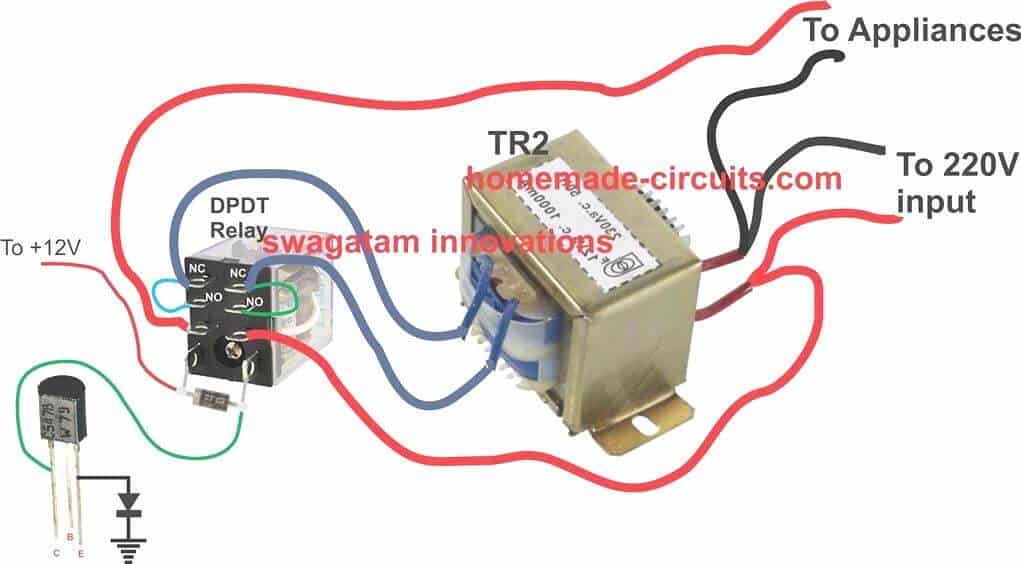
The relay, which is a DPDT type of relay, has its contacts wired up to a transformer, which is an ordinary transformer modified to perform the function of a stabilizer transformer.
It’s primary and secondary winding are interconnected in such a manner that through appropriate switching of its taps, the transformer is able to add or deduct a certain magnitude of AC mains voltage and produce the resultant to the output connected load.
The relay contacts are appropriately integrated to the transformer taps for executing the above actions as per the commands given by the opamp output.
So if the input AC voltage tends to increase a set threshold value, the transformer deducts some voltage and tries to stop the voltage from reaching dangerous levels and vice versa during low voltage situations.
Complete Circuit Diagram
Transformer Relay Wiring Diagram
Parts List
You will require the following components to make this homemade automatic mains voltage stabilizer circuit:
- R1, R2 = 10K,
- R3 = 470K or 1M, (lower values will enable slower voltage corrections)
- C1 = 1000 uF / 25 V
- D1, D2, D3 = 1N4007,
- T1 = BC547,
- TR1 = 0 – 12 V, 500 mA,
- TR2 = 9 – 0 – 9 V, 5 Amp,
- IC1 = 741,
- Z1, Z2 = 4.7V/400mW
- Relay = DPDT, 12 V, 200 or more Ohms,Approximate Voltage Outputs for the Given Inputs
Stabilized Output Vs UnStabilized Input Voltage Proportions
INPUT------OUTPUT
200V -------- 212V
210V -------- 222V
220V -------- 232V
225V -------- 237V
230V -------- 218V
240V -------- 228V
250V -------- 238V
How to Set Up the Circuit
The discussed simple automatic voltage stabilizer circuit may be set up with the following steps:
Initially do not connect the transformers to the circuit, also keep R3 disconnected.
Now, using a variable power supply, power the circuit across C1, the positive of the supply goes to the pin#7 line of the opamp while the negative goes to the negative pin#4 line of the opamp.
Set the voltage to about 12.5 voltage and adjust the preset so that the output of the IC just becomes high and triggers the relay.
Remember, here we have assumed that the DC output 12.5V from TR1 corresponds to around 225V AC input from mains. For your circuit be sure to confirm this before doing this setup procedure.
Meaning, if suppose you find that your TR1 DC output corresponds to 13V for an input of 225V, then complete this procedure using 13V....and so on.
Now lowering the voltage to about 12 volts should make the opamp trip the relay to its original state or make it de-energized.
Repeat and check the relay action by altering the voltage from 12 to 13 volts, which should make the relay flip flop correspondingly.
Your setting up procedure is over.
Now you may connect both the transformer to its appropriate positions with the circuit, and also restore the R3 and the relay connections across their original points
Your simple home made mains voltage stabilizer circuit is ready.
When installed, the relay trips whenever the input voltage crosses 230 volts, bringing the output to 218 volts and keeps this distance continuously as the voltage reaches higher levels.
When the voltage drops back to 225, the relay gets de-energized pulling the voltage to 238 volts and maintains the difference as the voltage further goes down.
The above action keeps the output to the appliance well between 200 to 250 volts with fluctuations ranging from 180 to 265 volts.
Warning: A single wrong connection could lead to a fire hazard or explosion, therefore please proceed with caution.
Always use a 100 watt protection bulb in series with the one of the mains line which goes to the stabilizer transformer initially. Once the operations are confirmed, you can remove this bulb.
2) The entire circuit is not isolated from mains, therefore users are advised to maintain extreme caution while testing the unit in an uncovered position and while powered ON, to avoid lethal electric shocks.



Questions & Answers
hello sir.. please is it possible to use SPDT relay instead of using the exact one that is use for this specific project DPDT?…. if yes please is their any adjustment for the circuit?
Hello Yusuf,
If you want to use SPDT relays, you can connect their coils in parallel, and wire up their contacts in the same way as done for the DPDT contacts. No other adjustments would be required…
Hello sir, please what is the exact rating of the DPDT relay which I knew the voltage is 12v but what about the amp?
Thank you
Hello Yusuf,
The rating of the DPDT relay will depend on the wattage of the connected load, and its rating should be printed on the body of the relay…
hermano como seria ese circuito para un voltaje de 115vac. Venezuela.
sometimes when I starts geyser a sound comes out of fridge stabilizer. It is not happening all the time I starts geyser. otherwise fridge stabilizer is working all right without any sound. why it is? is the stabilizer is not working properly and required to be replaced by new one.
Please check the AC voltage when you switch ON the geyser and if the stabilizer makes noise, if you find the voltage is dropping, then it could be due to to low voltage…
A noble endeavor, much appreciated, quite a learning to see your projects. Plz keep up the good work. Thank you.
Khalid Mahmood Gorsi.
Hello sir I really appreciate your effort
Please sir if I’m to connect LED how is the connection going to be?
Thank you sir
Hello Yusuf, you can replace the Z2 with an LED, but with opposite polarity.
Thank you for your kind words!
dear swagatam pls I need a circuit diagram of an adjustable ac power supply for testing some things
Miracle, For an adjustable AC power output you will need a variac, there’s no other proper alternative to this.
Sir if you have done any simulations on these stabilizer could you please share 🙏
Hello Sonam,
I did not do any simulations so far, however i have tested the design, and it worked well for me.
Noted sir thanks
Is this must work if we made the connections all right
Yes, it is a tested design…
My relay is 24 volts. What should I change in the circuit to make it work on 24 volts?
dear swagatam how many watts of load can it handle?
Hi Okongwu, the power capacity of the stabilizer depends on the wattage of transformer TR2. You can upgrade it as per your load capacity.
You will have to change the TR1 transformer and the op amp. Use a 0-24V 500 mA transformer and use one op amp from LM358
Hello,
Can anyone explain to me the connection of opamp “3” to “P1??” (i don’t know about this P1 because there is no P1 in the components, i assume that it is an R1).
Can anyone clarify this for me?? Thanks
Sorry for the confusion. P1 is a preset or a trimpot as shown in the following figure:
It is not R1.
And Finally, What will be my preset setting for this?
Unfortunately you will need a variac for the setup. Set the AC input voltage at 240V and then adjust the preset until the relay just activates or switches ON.
okay.. so i will need to dial the 10k ohms VR for it to punch the relay..
You can adjust the P1 preset in the following way.
Keep R3 disconnected and keep the wiper of P1 to ground level.
Feed 240V or 245V AC supply at the input.
Now slowly adjust P1 until the relay just clicks in (switches ON)
Now try reducing the AC input, you will find that the relay switches OFF again within a 5V space.
Put R3 back, now the switch ON /switch OFF difference should increase by 10V depending on the value of R3.
Alright! Thanks for replying so fast on my query.. cheers on you mate!
You are welcome!
I see, Thank you for the clarification.
And one more thing, How many outlets i can make through this?
I am planning to put my CPU and Monitor.. So, i will create 2 parallel output for my computer and monitor.
Is this okay. it will not burn up?
You can use two outlets, one for PC and one for monitor, but then the transformer TR2 must be rated at at least 7 amps
Oh damn! i already bought the 5A transformer.. Can i just get the 10A then?
Yes, I think 10 amp will be quite safe, and there will be no voltage drop.
I was in need of the components to buy
Good evening sir am a physics student am requesting you to give me the functions of each part in that circuit diagram. thanks much
My question is what is the wattage of the stabilizer in the above circuit. This will enable me upgrade in future
Ok sir thanks for that information. Does it mean that the above stabilizer can be taken be within 1000watts (i.e. 5A *220v = 1100VA).
The 5A is for the secondary winding, meaning for the voltage which is being added or subtracted with the mains voltage. So if the secondary is 12V, then multiplying 5A with 12V gives 60 watts. so the maximum capacity of the stabilizer will be 60 watt, and so on.
wattage will depend on the rating of the transformer. Multiplying the current and voltage specs of the transformer will give the wattage of the stabilizer
Thanks for the detailed explanation.
I guess a capacitor droper for the 12V control circuit can work, am I right?
I am also thinking of a multi-stage one to keep the tolerance minimized. with a 12V and a 6V and mean voltage of 225 the results would be:
input –> output
200 –> 218
210 –> 228
220 –> 226
230 –> 224
240 –> 222
250 –> 232
Is there any other option for this than multi staging?
Do you mean capacitive power supply, to avoid the left side transformer? I won’t recommend that….because a transformer based power supply works better in this design.
12V and 6V step-up, step-down separately can be very difficult to include in this design, it might not be feasible in this small configuration
Good Day Sir. How many watts load can the stabilizer above withstand? Also, what can I do to enable the set up above pick from 150v. Thanks.
Good day Onyi, the power handling capacity of the stabilizer will depend on the relay contact rating and the transformer rating.
For 150V boosting, you will have to use a transformer that can support upto +/- 50V boost and cut
Hello, good afternoon, could you put a picture of how two simple inverter relays are connected. Because a double relay is very difficult to get here. Thank you
I’m using circuit wizard to simulate this circuit. I’m just a little confused about the connection of the relay and TR2. Does the pin of both NO and NC of the relay shorted and connected to the secondary pin of TR2?
You have done a very good job.
Thank you!