Here we will study the design of a simple automatic mains AC voltage stabilizer which can be applied for safeguarding appliances like TV and refrigerators from fluctuating voltages.
A voltage stabilizer is a device which is designed to sense inappropriate voltage fluctuations in AC mains supply inputs, and correct them to produce a stabilized voltage for the connected appliances or gadgets.
How the Circuit Functions
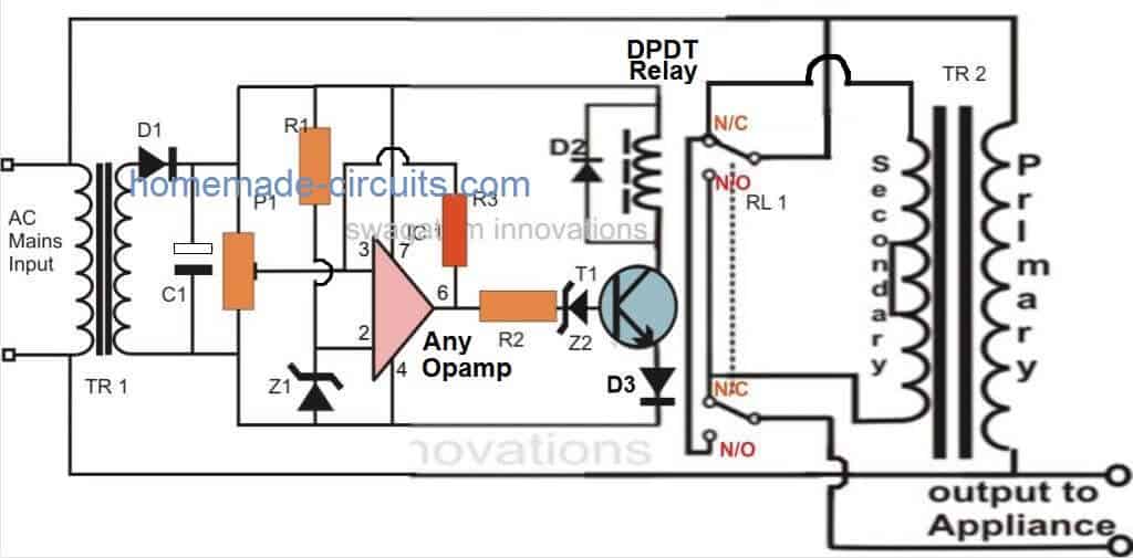
Referring to the figure we find that the proposed automatic voltage stabilizer circuit is configured with the single opamp IC 741. It becomes the control section of the whole design.The opamp is wired as a comparator, we all know how well this mode suits the IC 741 and other opamps. It's two inputs are suitable rigged for the said operations.
Pin #2 of the IC is clamped to a reference level, created by the resistor R1 and the zener diode, while pin #3 is applied with the sample voltage from the transformer or the supply source.
This voltage becomes the sensing voltage for the IC and is directly proportional to the varying AC input of our mains supply.
The preset is used to set the triggering point or the threshold point at which the voltage may be assumed to be dangerous or inappropriate. We will discuss this in the setting up procedure section.
The pin #6 which is the output of the IC, goes high as soon as pin #3 reaches the set point and activates the transistor/relay stage.
In case the the mains voltage crosses a predetermined threshold, the ICs non inverting detects it and its output immediately goes high, switching ON the transistor and the relay for the desired actions.
The relay, which is a DPDT type of relay, has its contacts wired up to a transformer, which is an ordinary transformer modified to perform the function of a stabilizer transformer.
It’s primary and secondary winding are interconnected in such a manner that through appropriate switching of its taps, the transformer is able to add or deduct a certain magnitude of AC mains voltage and produce the resultant to the output connected load.
The relay contacts are appropriately integrated to the transformer taps for executing the above actions as per the commands given by the opamp output.
So if the input AC voltage tends to increase a set threshold value, the transformer deducts some voltage and tries to stop the voltage from reaching dangerous levels and vice versa during low voltage situations.
Complete Circuit Diagram
Opamp Calculations
If a resistor divider was used instead of a zener at pin#2, the relationship between the reference level at pin#2 of the opamp with the resistor divider and Vcc could be given as:
Vref = (R2 / R1 + R2) x Vcc
Where R2 is the resistor used instead of Z1.
Op-Amp Hysteresis Resistor Calculations
To calculate the resistor values for an op-amp hysteresis circuit, we'll use the following formulas:
Upper Threshold Voltage (VTH):
VTH = VREF * (R1 + R2) / R1
Lower Threshold Voltage (VTL):
VTL = VREF * R2 / R1
Hysteresis Voltage (VHYS):
VHYS = VTH - VTL = VREF * R2 / R1
Where:
- VTH: Upper threshold voltage
- VTL: Lower threshold voltage
- VHYS: Hysteresis voltage
- VREF: Reference voltage (usually the supply voltage or a voltage divider output)
- R1: Resistor connected between the non-inverting input and ground
- R2: Resistor connected between the non-inverting input and the output
Transformer Relay Wiring Diagram
Parts List
You will require the following components to make this homemade automatic mains voltage stabilizer circuit:
- R1, R2 = 10K,
- R3 = 470K or 1M, (lower values will enable slower voltage corrections)
- C1 = 1000 uF / 25 V
- D1, D2, D3 = 1N4007,
- T1 = BC547,
- TR1 = 0 – 12 V, 500 mA,
- TR2 = 9 – 0 – 9 V, 5 Amp,
- IC1 = 741,
- Z1, Z2 = 4.7V/400mW
- Relay = DPDT, 12 V, 200 or more Ohms,Approximate Voltage Outputs for the Given Inputs
Stabilized Output Vs UnStabilized Input Voltage Proportions
INPUT------OUTPUT
200V -------- 212V
210V -------- 222V
220V -------- 232V
225V -------- 237V
230V -------- 218V
240V -------- 228V
250V -------- 238V
How to Set Up the Circuit
The discussed simple automatic voltage stabilizer circuit may be set up with the following steps:
Initially do not connect the transformers to the circuit, also keep R3 disconnected.
Now, using a variable power supply, power the circuit across C1, the positive of the supply goes to the pin#7 line of the opamp while the negative goes to the negative pin#4 line of the opamp.
Set the voltage to about 12.5 voltage and adjust the preset so that the output of the IC just becomes high and triggers the relay.
Remember, here we have assumed that the DC output 12.5V from TR1 corresponds to around 225V AC input from mains. For your circuit be sure to confirm this before doing this setup procedure.
Meaning, if suppose you find that your TR1 DC output corresponds to 13V for an input of 225V, then complete this procedure using 13V....and so on.
Now lowering the voltage to about 12 volts should make the opamp trip the relay to its original state or make it de-energized.
Repeat and check the relay action by altering the voltage from 12 to 13 volts, which should make the relay flip flop correspondingly.
Your setting up procedure is over.
Now you may connect both the transformer to its appropriate positions with the circuit, and also restore the R3 and the relay connections across their original points
Your simple home made mains voltage stabilizer circuit is ready.
When installed, the relay trips whenever the input voltage crosses 230 volts, bringing the output to 218 volts and keeps this distance continuously as the voltage reaches higher levels.
When the voltage drops back to 225, the relay gets de-energized pulling the voltage to 238 volts and maintains the difference as the voltage further goes down.
The above action keeps the output to the appliance well between 200 to 250 volts with fluctuations ranging from 180 to 265 volts.
Warning: A single wrong connection could lead to a fire hazard or explosion, therefore please proceed with caution.
Always use a 100 watt protection bulb in series with the one of the mains line which goes to the stabilizer transformer initially. Once the operations are confirmed, you can remove this bulb.
2) The entire circuit is not isolated from mains, therefore users are advised to maintain extreme caution while testing the unit in an uncovered position and while powered ON, to avoid lethal electric shocks.


Questions & Answers
Sir i have a voltage fluctuation problem at my house so my 18 watt tube gets blown off again and again in short period of time so i wanted to know is there any modification to be done in the Electronic ballast for protection such as a fuse or something like that?? Please suggest me sir….
hi sir i build this circuit but it don't work sir i connected everything properly,sir you show T2 as a centertap 9-0-9 but in the circuit it don't connect to anywhere please i need your help sir thank you.How to Make a Small Homemade Automatic Voltage Stabilizer for TV sets and Refrigerator
Hi zinnaboy, T2 is a 0-18v trafo which can be achieved by using a 9-0-9 trafo with center tap shorted. the center tap does not connect anywhere.
The circuit will definitely work if the settings are done correctly, and if the circuit is built without errors.
Hi sir i forgot something so the 2 relay have to switch same time when the circuit is power? (2nd)question please where is the relay coil i can only see 1 coil or its should be ignore (3rd)question can i set the circuit without variable power supply? thank you sir please don't ignore my question stay bless.
Hi zinnaboy, yes both the relays should operate together, preferably it should be a DPDT type meaning a relay having double sets of contacts but a single common coil. That's why you can see only one coil.
If you want to use two separate relays then you can simply connect both the coils parallel with each other across D2
You cannot set it without a variable power supply. It will be required.
How to Make a very Small Homemade Automatic Voltage Stabilizer that could be place along with led lights just before the LED drivers. it could be like pocket size compact .
You can use LM317 or LM338 IC for it.
hi Swagatam
frnd i want a circuit diagram of automatic voltage stabiliezer
Hi Jwalant,
please see the list of stabilizer circuit images at the end of the above article, you can select any one of those
Is this use for induction stove…
Is this useful for induction stove.. if not then pls give idea for me
yes, make sure the trafo is appropriately rated to handle the induction stove current.
hello mr swagatam, I'm looking to make a very high power voltage regulator, DC to DC. the required voltage is nearly 380 (moteur triphasé), any advices or simple shematic that could help. thank you
my email IDs are given in the "contact" page.
hello my name is ariel of buenos aires Argentina. can you help me?
in my area there are always low voltage 185 / 190vca .. I have a transformer 12v x 10 amps .. the question is: how I can connect to climb a little tansion …
from already thank you very much.
ATTE. ariel from Argentina.
hello ariel, your transformer will produce an increase of only 12V, meaning if the mains level is at 185, adding your trafo voltage will make it just 185 + 12 = 197V
Buy a 12-0-12V/10amp trafo, this will boost the voltage to a useful level…i'll explain you how to do once you get it.
Sir,
can i use this stabilizer for 230-240V AC?? can i stabilize my refrigerator or tv or speaker system from it ???
Plzz tell??
can i use this circuit for AC voltage 220 and for stabilizing refridgerator or tv set???
Muzamil, yes you can use the above shown circuit for safeguarding TV, fridge etc, but the transformer TR2 will need to be upgraded as per the load amp rating.
HI Mr.Swagatam Majumdar how are you,
You have good experience in electronics,I need hex cod pic 16f676, 5 step automatic voltage stabilizer with circuits diagram.I will be very thank full to you.
Regards.
Thanks Irfan, I'll try to get the codes and the diagram, if possible, and let you know.
Thanks a lot dear.
Thanks a lot dear, can you give me your Facebook ID that is easy for me.
Irfan, I don't visit FB very often, so my blog is the best place to interact. We can chat here just as I am doing with other dedicated members…
i have circuit but don't have pic16f676 hex cod what can i do????
I am sorry, I don't have much knowledge regarding MCU coding, so won't be able to provide the required info to you
Good,,,ok no problem i will figure it out my self…take care…
Regards..
Hi,
How are you Mr.Swagatam Majumdar. Can give me this circuit diagram?
Regards…
sir, pls give me guidelines of connection of TR2 and how this TR2 works?
I have a stabilizer of 1KV of output Voltage Range of 220-240,but of late it produces output range of 250 -260…..why and how can i cure it…plz help
it could be happening due to any of the two reasons, either you have changed your battery with a new one and therefore the full charge of the battery is causing the extra voltage or the internal voltage correction setting is disturbed due to some reason…you can also check with a some kind of load connected and see if the voltage drops…
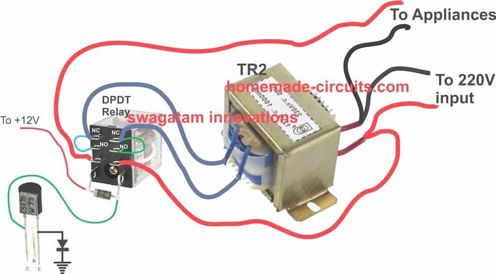
sir i am having trouble connecting relay to the circuit.. i have dpdt 8pin relay and its pin configuration. sadly i cant get to wire it correctly can you please simplify by telling the connection scheme..like the collector of transistor is connected to COIL OF relay…
2) how can i use 2 SPDT relays 5 terminals instead of 1 DPDT 8terminals
Asim, if you want to use 2 SPDT relays, then you just have to connect the relay coils of both the relays in parallel across the collector/positive line as shown in the diagram.
as for the contacts, first identify the N/C, N/O and pole of the two relays, then simply join their N/C, N/C….N/O, N/O, and pole, pole together, and finally wire the common ends of these contacts to the transformer as indicated in the diagram.
thank you soo much for the help sir,let me assemble it 🙂
when i am trying to calibrate the cicuit the relay is flickering even on 11-13v supply and the preset seems to be not doing anything at all
please elaborate the callibration process please
keep the relay disconnected while calibrating, use an LED indication instead, for fixing the cut-off threshold, once the setting up is completed you can connect the relay back
keep R3 disconnected while calibrating, reconnect it once the calibration is done.
connect LED in series with Z2
sir , do i have to connect TR1 as (12v,0) configuration ,or do i have to connect it in (12,-12) wired configuration ?
Hello Sir, 8-pin DPST Relay Is Not Available In My Area, Can U Pls Tel Me Whether I Can Use 4 Pin Spst Relay Instead?
hello solmon, you can two SPST relays in parallel
hello sir, can tr2 be the same as tr1? so that it produce 12 v buck and 12v boost?
No, TR1 can be a small 0-12V 500mA trafo, while TR2 is supposed to be the main stabilizer trafo and should be rated at 5 amps minimum, 12-0-12V
what is the suitable size of the cable to connect the tr1 and the supply?
Dear Swagtam, please reply me as soon as possible I mailed you but got no reply. Kindly Sir help me what is N/C and N/O in diagram??and what is relation between stabilizer transformer and comparator circuit. and also what is suitable value for inductor placed parallel in D2. Sir please help me as soon as possible.
Dear Ali, it seems you are very new to electronics and therefore you seriously need to learn the basics first and then attempt this circuit or any other circuit, otherwise you may fail to succeed in building these circuits.
The inductor with D2 is not a separate inductor, rather it is coil of the relay. The N/C and N/O are the twin contacts of a DPDT relay, in a DPDT relay the coil is single but the contacts are in pair.
for more information about relays you an refer to the following post
https://www.homemade-circuits.com/how-to-understand-and-use-relay-in/
heloo .. i am a physics student…
i would like to know what is the inductor like thing alond diode d2.. pls give its configuration
It is the relay coil…D1 is the freewheeling diode for the relay coil which protects T1 from the back EMFs generated by the relay coil
Hello sir, long time. regards to you. I need a 5kva voltage stabilizer circuit with atleast 3 or 4 relays, using ic either Lm324 or 556 dual timer, with indicators of boost, buck and normal voltage. Pls send me the circuit diagram to my email.
Thanks solomon, you can try the concept presented in the following article:
https://www.homemade-circuits.com/5-kva-to-10-kva-automatic-voltage-stabilizer-circuit/
You can modify the transformer wattage according to your own specifications. You will need a variac for testing the results
Thank u sir, i appreciate
Please sir, can I get an op amp circuit for step down transformer which will have a fixed secondary voltage for input voltage range from 150v – 250v. Thanks
Glory, fixed voltage may not be possible, it will slightly change with respect to input fluctuations
OK sir, can I get any op amp differential circuit, for such slight change in output voltage.
glory, the output voltage is determined by the transformer tap selection not by the opamps
Sir, what I am asking for is that my AC mains varies from 150-250v which affect the trafo output. When I plugged a voltage stabilizer, at high AC mains, the trafo gets very hot. So I need a circuit that can pick an appropriate tapping on trafo, for better efficiency of the trafo.
In that case you will require a 7 to 10 tap transformer and opamp stages, you can refer to the following link and upgrade the design as per your specific needs:
https://www.homemade-circuits.com/community/electronic-circuit-forum/5-kva-to-10-kva-automatic-voltage-stabilizer-circuit/
I have no problems assemblying the circuit so far as the diagram is correct i can follow everything and do the assembly… but my question is,
Can this stabilizer carry the entire house, do the stabilizer have a wattage range? i intend to make it and stabilize my entire house and equipment… your help will be welcomed sir.
yes it can be used for whole house voltage regulation, by upgrading the the transformer and the relay according to your house’s maximum load specifications
Thanks for writing back sir.
So how do i go about upgrading the transformer? at least i understand that i will need to upgrade the 5A transformer if i am not wrong, if i can recoil any transformer secondary to give me 15A, will that work? i look forward to be hearing from you.
Yes that’s right, if your entire home electrical load is less than 10 amps then 15 amp transformer should work
Thank you very much sir.
now if i may ask, how can i identify the amps of the equipments i have in the house? am i to just calculate all the amps and total it or how, Then what will be the effects if the amps is low? will it cause low voltage? the coils i fine in my area can deliver only 2amps so what if i twist it 5 in paralel, will that be able to give me 10amps or above.
thanks for your help and understandings.
Hi Nkwenti,
you can easily find the wattage of the appliances by referring to the back side labels of the respective appliances. You may note down the wattage specifications of the appliances from these labels, then add them up and divided this value with 220V or 120V as per the AC mains specs of your house. This will allow you to get the total maximum current requirement for your all house appliances.
yes if the stabilizer transformer is not rated at twice the rating of your house’s total current consumption, then that might result in incorrect voltage stabilization from the unit…
Thank you sir for giving me your time and also teaching me the theory in details, youre trully a teacher, ok my problem is how to push the transformer to carry atleast 1500watts load so to be sure, now, please sir, have you any idea of the secondary coil guage of the transformer? i can do the coiling but dont know the exact guage, the coils i see that can be used for the secondary of the transformer which that is the important role can deliver only 2 to 3 amps, if i double the coils tho it will be in isolated mode, can that increase the amperes ratings that may be able to match my need? thanks for your help, youre not only an innovator but a teacher.
Nkwenti
Thank you Nkwenti, I am sorry I do not have any expertise in the field of transformer winding, you may have to consult a professional transformer designer.
Or you may open a 500 watt transformer and check the relevant wires gauges, and simply make it 3 times higher for your 1500 watt transformer.
hello what is use of coil connected to d2 which is connected across
that is the coil of the relay.
I did not understand the setting up procedure…you said that positive goes to the terminal of R1 …but which terminal of R1? and if i disconnect the relay then how will i understand that there is enough voltage to trigger the relay?
I have changed the explanation for better understanding, please check it now….
Thank you for your replay… Now If i disconnect the relay , how will i understand that the output is high enough to trigger the relay? is output will be 12v?
For the setting up procedure you will need an external variable power supply, once the set up procedure is complete after that you can connect TR1, TR2 and finalize the design.
Relay should not be disconnected, it seems to be a mistake, I’ll correct it soon…actually I meant to say keep the relay contacts disconnected with everything..anyway I’ll change it soon
thank you..
Hello could you put a picture or picture of the connection of 2 relay Spdt .. Thank you very much
You can find the details of an SPDT relay in this article:
https://www.homemade-circuits.com/how-a-relay-works-in-circuits-how-to-connect-it/
Hello good afternoon. I have a problem with 2 circuits the 2 are 9vcc. The problem is that when I feed them with separate sources they work well, but when I feed them with the same source they do not work well. The source voltage is correct. I really do not know what it can be. From already thank you very much.
Please show me the schematics or provide detailed info about the technical specs of the two circuits.
How can the secondary and primary of the (second) auto-transformer be connected together to the mains AC input voltage. The specification says it’s a 12-0-12 volt and the primary is 220volt. Won’t it get burned does to insulation puncture. Thank you in advance for your reply.
The secondary and primary are added in series by the relay contact combinations, the secondary is never connected directly across the 220V mains.
Thank you for your quick reply. And will it be able to run a load of suppose a table fan i.e 150 watts because primary has high resistance and thinner wire than secondary so current will be limited to the primary’s rating.
what is the workaround for this. Thank you in advance again.
To support a 150 watt load, the transformer should be also rated at 150 watts, otherwise it may become hot or even burn. A 12V 150 watt transformer would mean the secondary side having 150/12 = 12 amp rating, and the primary side 150/220 = 0.68 amps
You have done a very good job.
Thank you!
I’m using circuit wizard to simulate this circuit. I’m just a little confused about the connection of the relay and TR2. Does the pin of both NO and NC of the relay shorted and connected to the secondary pin of TR2?
Hello, good afternoon, could you put a picture of how two simple inverter relays are connected. Because a double relay is very difficult to get here. Thank you
Good Day Sir. How many watts load can the stabilizer above withstand? Also, what can I do to enable the set up above pick from 150v. Thanks.
Good day Onyi, the power handling capacity of the stabilizer will depend on the relay contact rating and the transformer rating.
For 150V boosting, you will have to use a transformer that can support upto +/- 50V boost and cut
Thanks for the detailed explanation.
I guess a capacitor droper for the 12V control circuit can work, am I right?
I am also thinking of a multi-stage one to keep the tolerance minimized. with a 12V and a 6V and mean voltage of 225 the results would be:
input –> output
200 –> 218
210 –> 228
220 –> 226
230 –> 224
240 –> 222
250 –> 232
Is there any other option for this than multi staging?
Do you mean capacitive power supply, to avoid the left side transformer? I won’t recommend that….because a transformer based power supply works better in this design.
12V and 6V step-up, step-down separately can be very difficult to include in this design, it might not be feasible in this small configuration
My question is what is the wattage of the stabilizer in the above circuit. This will enable me upgrade in future
wattage will depend on the rating of the transformer. Multiplying the current and voltage specs of the transformer will give the wattage of the stabilizer
Ok sir thanks for that information. Does it mean that the above stabilizer can be taken be within 1000watts (i.e. 5A *220v = 1100VA).
The 5A is for the secondary winding, meaning for the voltage which is being added or subtracted with the mains voltage. So if the secondary is 12V, then multiplying 5A with 12V gives 60 watts. so the maximum capacity of the stabilizer will be 60 watt, and so on.
Good evening sir am a physics student am requesting you to give me the functions of each part in that circuit diagram. thanks much
I was in need of the components to buy
Hello,
Can anyone explain to me the connection of opamp “3” to “P1??” (i don’t know about this P1 because there is no P1 in the components, i assume that it is an R1).
Can anyone clarify this for me?? Thanks
Sorry for the confusion. P1 is a preset or a trimpot as shown in the following figure:
It is not R1.
I see, Thank you for the clarification.
And one more thing, How many outlets i can make through this?
I am planning to put my CPU and Monitor.. So, i will create 2 parallel output for my computer and monitor.
Is this okay. it will not burn up?
You can use two outlets, one for PC and one for monitor, but then the transformer TR2 must be rated at at least 7 amps
And Finally, What will be my preset setting for this?
Unfortunately you will need a variac for the setup. Set the AC input voltage at 240V and then adjust the preset until the relay just activates or switches ON.