An LED tube-light is lighting device built using high efficiency LEDs for illuminating a premise where it is installed, through the available AC mains supply.
In this post I have explained the complete construction details of a simple LED light tube light circuit using 20 mA, 5 mm high bright white LEDs.
The circuit can be operated directly from the 230V AC mains of your domestic supply. This will not only save electric power but also help curb the global warming issue.
WARNING: SINCE ALL THE CIRCUITS EXPLAINED BELOW INVOLVE LETHAL HIGH MAINS AC VOLTAGES, WE STRICTLY ADVISE YOU NOT TO BUILD THESE CIRCUITS UNLESS YOU ARE TOTALLY AWARE OF THE DANGERS OF AC MAINS VOLTAGES AND EXACTLY KNOW HOW TO SAFEGUARD YOURSELF BY EXERCISING PROPER SAFETY MEASURES, WHILE BUILDING THESE CIRCUITS.
LED Tube light using a Transformer or Battery
In the following first design we will see how to make a simple lED tubelight using a transformer based power supply, and by connecting the desired number of LEDs in series parallel connection.
Using white LEDs for illuminating our homes is becoming popular nowadays, due to the high power efficiency involved with these devices.
The diagram shows a straightforward configuration involving many LEDs, arranged in series and parallel.
Circuits Description
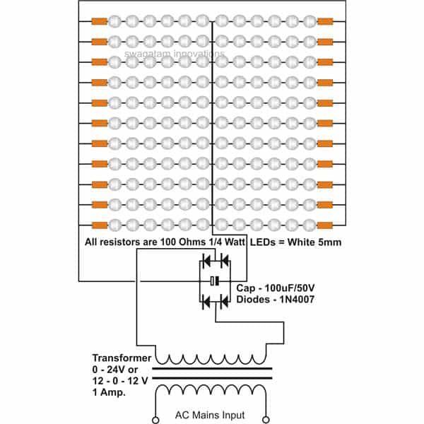
Referring to the shown LED tube light circuit using transformer we see the LEDs are driven by a general purpose 24 V power supply for illuminating the LED bank very brightly.
The power supply incorporates standard bridge and capacitor network for the required rectification and filtration of the supply voltage to the LEDs.
The arrangement of the LEDs is done in the following way:
The supply voltage being 24, dividing it by the forward voltage of a white LED which is around 3 volts gives 24/3 = 6, meaning the supply voltage will be able to support at the most 6 LEDs in series.
However since we are interested to include many LEDs (132 here), we need to connect many of these series connected strings of LED through parallel connections.
That's exactly what we do here.
Total 22 strings of LEDs having 6 in each are connected in parallel, as shown in the figure.
Since current limiting becomes an important issue with the white LEDs, a limiting resistor is added in series with each of the strings.
The value of the resistor may be optimized by the user for adjusting the overall illumination of the LED tube light.
The proposed design will provide enough light for illuminating a small 10 by 10 room brightly, and will consume not more than 0.02 * 22 = 0.44 Amps or 0.44 * 24 = 10.56 watts of power.
24 Volt, LED Tube Light Circuit Using Transformer, Circuit Diagram
In the above designs we have learned how to make LED tube light without any current control which may be OK if the LEDs are not power LEDs and do not have the property of getting too hot due the extremely high bright illumination.
However for power LEDs which are designed to emit extremely high bright lights and which have the tendency to become too warm quickly, a heatsink and a current control feature become very important.
Transformerless LED Tube light Circuit with Constant Current for Power Saving
Current control in an LED tube light becomes crucial because LEDs are current sensitive devices and can quickly get into a thermal runaway situation, ultimately damaging it permanently.
In an LED thermal runaway situation the LED starts drawing more current, and begins getting warmer due to the absence of a current control limit.
The rising heat inside the LED forces the LED to draw even more current, which in turn cause more heat, this goes on until the LED is completely burnt and destroyed. This phenomenon is known as thermal runaway situation in an LED.
To avoid this current control becomes too crucial for any LED driver circuit.
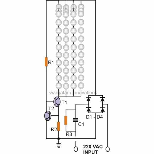
In this circuit resistor R2 is placed for converting the rising current to voltage across itself.
This voltage is sensed by R2 which immediately conducts and grounds T1's base rendering it inactive, the instantaneous process initiates a switching effect, producing the desired current control and safeguarding of the LEDs.
Each channel consists of 50 white LEDs in series. R2 is calculated with the following formula: R = 0.7 / I, where I = Total safe current consumed by the LEDs.
The whole circuit of the current controlled LED tube light may be understood in this manner:
Circuit Operation
When input AC is applied to the circuit, C1 drops the input current down to a lower level which can be considered to be safe for operating the involved electronic circuit.
The diodes rectify the low current AC and feeds to the next current sensing stage consisting of T1 and T2.
Initially T1 is biased through R1 and conducts fully illuminating the entire array of LEDs.
As long as the current delivered by T1 or rather current drawn by the LEDs is within the specified safe limit, T2 remains in a non-conducting state, however of the current drawn by the LEDs begins to cross the safe limit, the voltage across the limiting resistor R2 begins to develop a small voltage across it.
When this voltage exceeds 0.6, T2 begins to leak through its collector emitter pin outs.
Since the collector of T2 is connected to the base of T1, the biasing current to T1 now starts leaking to ground.
This inhibits T1 from conducting fully and its collector current stops rising any further. Since the LEDs form the collector load of T1, the current through the LEDs also gets restricted and the devices are safeguarded from the rising current intake.
Ths above rise in the current takes place when the input AC rises, producing an equivalent increase in the LED current consumption, but the inclusion of T1 and T2, ensures that anything that's dangerous to the LEDs is effectively controlled and curbed.
Parts List
Parts List for the proposed current controlled LED tube light circuit
| Component | Specification |
|---|---|
| T1 | MJE13003 |
| T2 | MJE304 |
| R1, R2 | To be calculated |
| R3 | 1 M, 1/4 W |
| Diodes | 1N4007 |
| C1 | 2 µF / 400 V |
Important Calculations
Capacitive Reactance of C1
The input capacitor (C1) is used to drop the 220V AC mains voltage and current to a lower level suitable for the LED array. The current through the LEDs depends on the capacitive reactance of C1.
Formula for capacitive reactance:
Xc = 1 / (2 * π * f * C)
Where:
Xc = Capacitive reactance (in ohms)
f = Frequency of AC mains (50 Hz or 60 Hz)
C = Capacitance of C1 (in Farads)
Example:
For C1 = 2 µF (2 × 10⁻⁶ F) and f = 50 Hz:
Xc = 1 / (2 * π * 50 * 2 × 10-6)
Xc ≈ 1591.55 Ω
Current Through the LED String
The current is determined by the voltage across the capacitor and the reactance.
Formula for current:
I = V / Xc
Where:
I = Current through the LEDs (in Amps)
V = RMS mains voltage (e.g., 220V AC)
Xc = Capacitive reactance (calculated above)
Example:
For V = 220V and Xc ≈ 1591.55 Ω:
I = 220 / 1591.55
I ≈ 0.138 A or 138 mA
This current value will flow through the LED array and should match the LEDs maximum current rating.
Power Dissipation in LEDs
The power dissipation in the LED string can be calculated as:
P = I × VLED
Where:
P = Power dissipation (in Watts)
I = Current through the LEDs (calculated above)
VLED = Total forward voltage of the LED string
Example:
For 20 LEDs in series with each having a forward voltage of 3V, VLED = 20 × 3 = 60V.
If I = 138 mA (from the previous calculation):
P = 0.138 × 60
P ≈ 8.28 W
Resistor Calculations (R1, R2, and R3)
R1: Limits the base current for T1. Its value depends on the LED string specifications.
Formula for Base Current (IB):
IB = ILED / hFE
Where:
ILED = 120 mA = 0.12 A (desired LED current)
hFE: Current gain of T1 (from the MJE13003 datasheet, hFE ≈ 20 at this current level)
Calculation for IB:
IB = 0.12 / 20 = 0.006 A = 6 mA
Formula for R1:
R1 = VB / IB
Where:
VB = 0.7 V (typical base-emitter voltage drop of T1)
IB = 6 mA
Calculation for R1:
R1 = 0.7 / 0.006 = 116.67 Ω
Choose the nearest standard resistor value:
R1 ≈ 120 Ω
R2: Act as current sensing resistors for T2 to ensure constant current for the LED.
Formula for R2:
R2 = Vsense / ILED
Where:
Vsense = 0.7 V (voltage required to trigger T2)
ILED = 120 mA = 0.12 A
Calculation for R2:
R2 = 0.7 / 0.12 = 5.83 Ω
Choose the nearest standard resistor value:
R2 ≈ 5.6 Ω
R3: Ensures that the high voltage capacitor is able to discharge, preventing painful shock to the user after the circuit is unplugged from the AC mains.
Formula for R3:
The discharge time constant is:
τ = R3 × C1
For a capacitor C1 = 2 μF and rectified voltage Vrectified = 311 V:
To ensure safe discharge within 1 second:
τ ≈ 1 s
Calculation for R3:
R3 = τ / C1 = 1 / (2 × 10⁻⁶) = 500,000 Ω
Choose the nearest standard resistor value:
R3 ≈ 470 kΩ
Bridge Rectifier (D1-D4)
The diodes (D1 to D4) form a bridge rectifier to convert the AC input to DC.
Each diode must handle:
Reverse voltage: At least the peak mains voltage, Vpeak = √2 × Vrms. For 220V AC, Vpeak ≈ 311V.
Forward current: Equal to the LED current, e.g., 138 mA.
Diodes like 1N4007 are suitable since they support 1000V reverse voltage and 1A forward current.
LED String Voltage and Current
Total forward voltage of the LED string: VLED = Number of LEDs × Forward voltage of a single LED.
Yo must ensure that the total forward voltage is less than the rectified DC voltage (approximately 311V for 220V AC input).
LED Specifications and Datasheet
| Parameter | Symbol | Value |
|---|---|---|
| Continuous Forward Current | IF | 120 mA assumed here, can be customized as required. |
| Peak Forward Current (Duty /10 @ 1KHZ) | IFP | 100 mA |
| Reverse Voltage | VR | 5 V |
| Operating Temperature | Topr | -40 ~ +85 ℃ |
| Storage Temperature | Tstg | -40 ~ +100 ℃ |
| Soldering Temperature (T=5 sec) | Tsol | 260 ± 5 ℃ |
| Power Dissipation | Pd | 100 mW |
| Zener Reverse Current | Iz | 100 mA |
| Electrostatic Discharge | ESD | 4 KV |
150 LED Transformerless LED Tubelight Circuit
The simple construction of an LED light tube light discussed here will not only save electric power but also if used in every house will help reduce the ever increasing global warming effects.
Today we are all aware regarding the bad effects of global warming and how it’s gripping our only planet day after day. But for this we ourselves are to be blamed.
You may be thinking how a common person can contribute to help solve the problem. Well look around you, yeah, it’s the lights that we are using presently generate quite an appreciable amount of heat to add to the global warming effect.
CFLs are considered to be quite efficient, but they too release quite a bit of heat. The issue can be very easily solved simply by transforming our heat producing lights into the "cool" white LED lights.
We will learn in this article how simple it is to build a LED light tube that can easily replace your existing "hot" fluorescent tube lights!
Parts List
You will require the following Parts for the construction:
One 36 inches long, 2 inches in diameter white PVC pipe,
150 Nos. White LEDs (5mm),
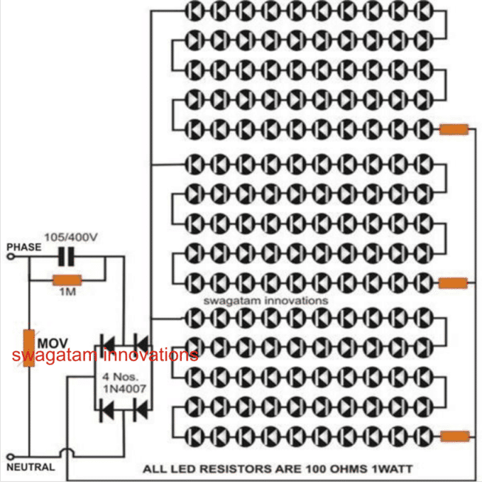
4 nos. 1N4007 diodes,
3 nos. 100 Ohms resistors,
1no. 1M resistor, 1/4 W CR 5%,
1no. Capacitor 105/400V, Polyester,
14/36 Wire for connections,
Soldering iron, solder wire etc.
Construction Clues
The construction of this circuit is carried out through the following simple procedures:
Cut the PVC pipe lengthwise into half.
Drill equally distributed LED size holes over the entire area of the two halves of PVC pipes. As shown in the diagrams just fix all the LEDS throughout the pipe.
Be sure to keep the position of the polarity of all the LEDs in the same orientation, Cut and bend the LED leads so that the leads touch each other side by side.
Make 3 series of 50 LEDS each by soldering the joints.
Make sure that each series comprises the given resistor of 470 Ohms.
Connect the 3 series LEDs groups in parallel by joining their positive and negative leads together through flexible wires.
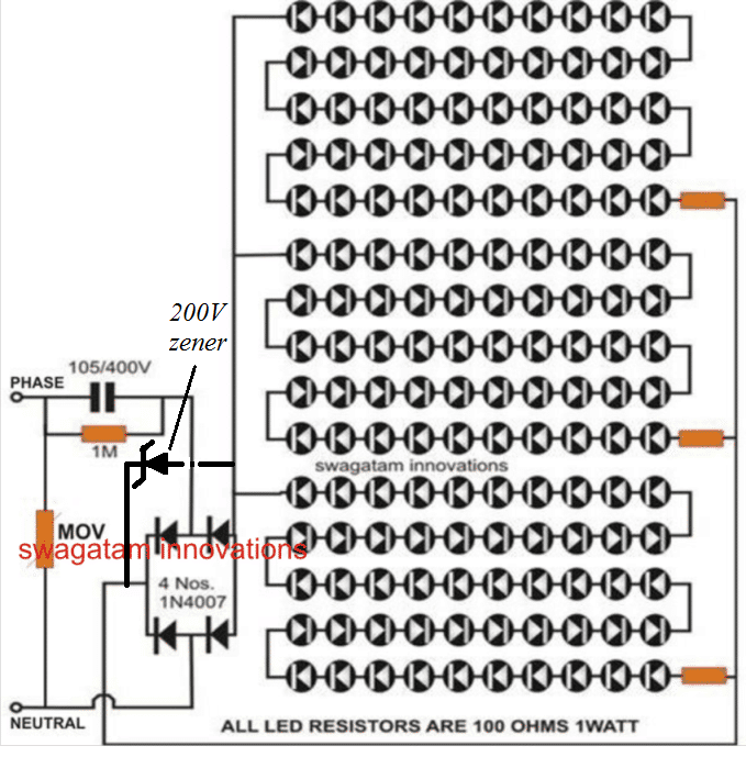
Make a bridge configuration rectifier by joining the 4 diodes together, and connect the relevant points to the LEDs and to a 2 pin mains cord, as shown in the figure.
How to Test it?
Testing this LED tube light circuit is probably the simplest part of the whole operation; it is done through the following simple steps:
After finishing the construction procedure as described above, just plug in the 2 pin plug into the mains socket (be extremely careful as the whole circuit may contain leakage currents).
Instantly all the LEDS should come ON giving a dazzling effect. If any of the series is dead or not glowing, switch OFF the power and check for the LEDs connected with wrong polarity.
Glue all the LEDs so that they may not come out of the holes I which they are inserted. Finally join the two halves of the PVC pipes with the LEDS, either by tying them or gluing them together with cynoacralite bond. Close the two open ends of the tube appropriately.
This concludes the construction of the LED light tube circuit. For optimum performance it would better to hang the unit from the ceiling so that the light is distributed equally.
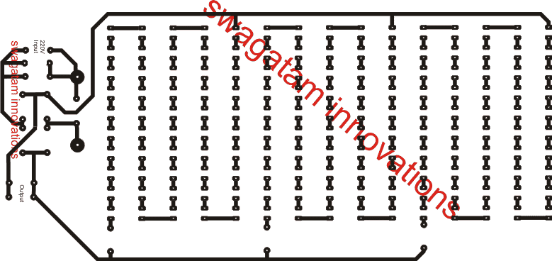
The PCB Design Layout for the above LED tube-light circuit can be seen in the following image.
Video Clip showing the testing of a similar LED tubelight using 108 LED in series parallel combination
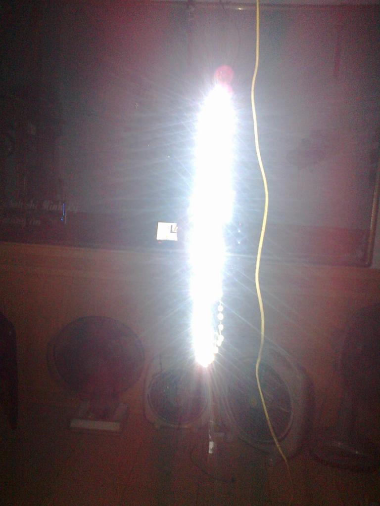
Below is a 50 LED Tube Light made by Merley, for your viewing pleasure:
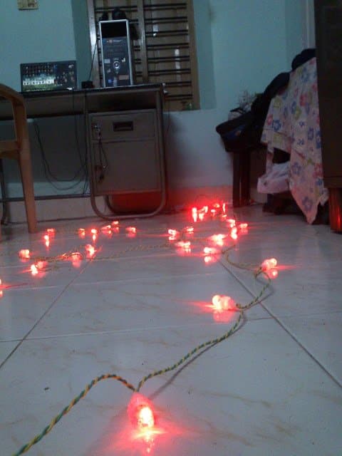
LED string light made by Mr.Bibin Edmond using the explained capacitive power supply.
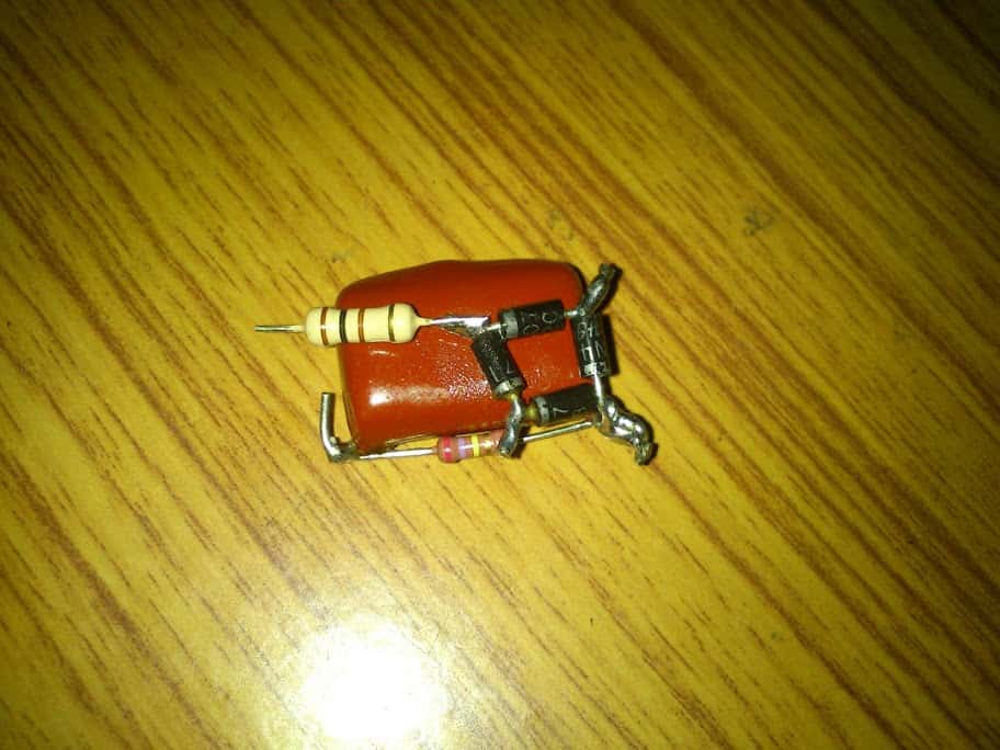
Here's the image of the simple capacitive PS circuit used for lighting the above string LED light.....
courtesy: Bibin Edmond
In case you think that a transformerless based LED tubelight may not be reliable or not powerful enough, you can opt for a transformer based power supply design for accomplishing the same, as described below.



Have a question or feedback? Feel free to ask below—just make sure it relates to the post above!