In this article we study a simple 3.7V li-ion battery charger circuit with auto-cut off, which can be charged from your computer USB port or any other 5 V regulated source.
Simplest 3.7V Li-ion Battery Charger with Auto Cut-off using LM393 IC
If you do not wish to read the following long explanation, you can just watch the same in this video:
How it Works
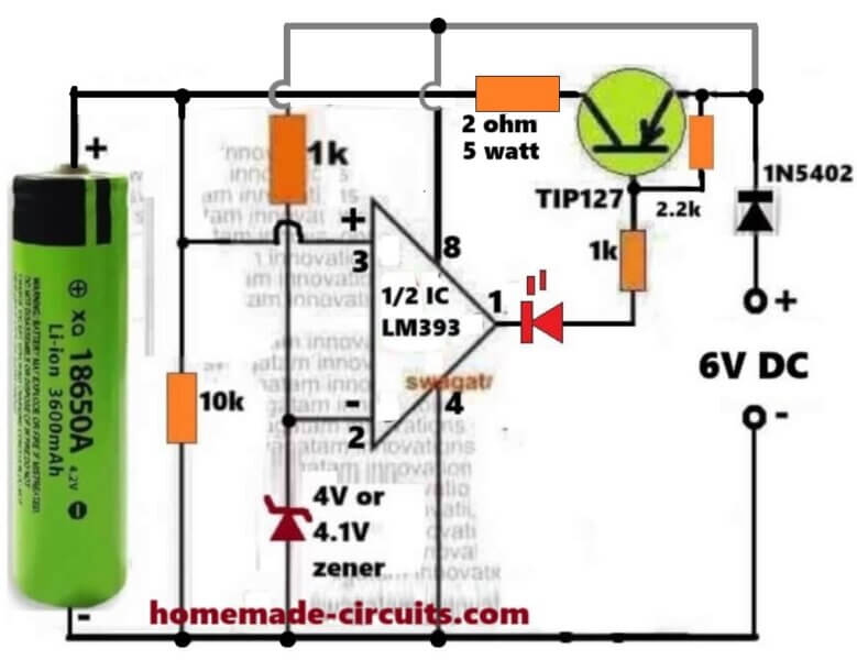
Here we see that this small circuit is made for charging one 3.7V Li-Ion cell like 18650 type, and we also see that it automatically stops the charging when the cell voltage becomes full around 4.1V or 4.2V.
So we can say that this is an automatic over charge protector using one half section of LM393 and one PNP transistor TIP127 which is working like a main current switch.
How The Whole Circuit Works Step By Step
Power Source And Battery Connection
We start by giving 6V DC supply to the circuit which acts like the charging input. The 3.7V battery is connected on the left side, so that the current flows from 6V supply through the TIP127 transistor to the battery for charging purpose.
Voltage Divider For Sensing Battery Level
The pin#3 of the LM393 is connected directly to the battery positive so it can sense the battery volatge level directly. So this way pin3 can sense the present battery level.
Reference Voltage From Zener Diode
We have one 4V or 4.1V zener diode connected to the inverting input pin2 of LM393. That zener is giving a fixed reference voltage which stays constant even if the battery voltage changes. So we can say that pin2 is having fixed 4.1V reference while pin3 is showing actual battery sample voltage.
Comparator Working Principle
Now we understand that LM393 is acting like one comparator, so it is comparing the voltages present at pin3 and pin2.
Case 1: Battery Voltage Is Low Or Discharged (below 4V or 4.1V)
So now that battery voltage is less than 4.1V, so voltage at pin3 is lower than voltage at pin2. Then the LM393 output transistor from inside becomes ON and it pulls pin1 to ground.
Because of this, pin1 becomes low and that low goes to the base of TIP127 through one 1k resistor. Since TIP127 is a PNP transistor, so its base getting low will make it conduct hard, so the current now starts flowing from emitter to collector and reaches the battery and the battery begins to get charged.
The LED also turns ON in this time because its cathode at pin1 goes to ground.
So we can now say in this condition:
LM393 output = LOW (Ground).
TIP127 = ON.
LED = ON.
Battery = Charging.
Case 2: Battery Voltage Is Full (4.1V Or 4.2V)
Now after sometime the battery gets almost charged, so that the voltage at pin3 becomes slightly higher than pin2. Then in this situation the internal transistor of LM393 turns OFF and its pin1 becomes open collector, that means pin#1 is now floating, without any logic level (open).
Now since pin1 is open, it cannot pull low anymore, so in this situation the 2.2k resistor now becomes active. That 2.2k resistor is connected from +6V to TIP127 base node so it pulls the base of TIP127 towards positive potential.
So when the base is pulled high and becomes near the emitter voltage, forces the TIP127 hard to stop conducting completely. So current cannot flow anymore from emitter to collector. The battery is disconnected from the charger. The LED also turns OFF because now there is no current path to ground through pin1.
So we can say now:
LM393 output = OPEN.
TIP127 = OFF.
LED = OFF.
Battery = Cut Off.
Role Of The 2.2k Resistor
Now we explain that 2.2k resistor which is very important here. It is actually working like a pull-up resistor, so that resistor is keeping the TIP127 base in one correct position depending on the output of LM393.
So when LM393 output is low, then that resistor becomes inactive because LM393 is grounding the base through the 1k resistor. So charging goes ON.
But when LM393 output is open then that 2.2k resistor pulls the TIP127 base high towards the emitter potential. So the transistor gets turned OFF strongly and it cannot conduct any leakage current. So this resistor ensures that the base never floats and the transistor never stays in half ON condition.
If that resistor is not there then the base of TIP127 may stay floating after LM393 goes open and this may allow some small leakage current to flow continuously, and the battery may keep trickle charging which is unsafe for Li-ion cell. So this 2.2k resistor saves the battery from such leakage problem.
Step By Step Summary Table
| Battery Condition | Pin3 Vs Pin2 | LM393 Output | Role Of 2.2k | TIP127 | LED | Battery |
|---|---|---|---|---|---|---|
| Low Or Discharged | Pin3 < Pin2 | Pin1 = Ground | Inactive | ON | ON | Charging |
| Fully Charged | Pin3 > Pin2 | Pin1 = Open | Active | OFF | OFF | Cut Off |
Main Points To Remember
So we now understand that LM393 works as one precise voltage comparator. The 4.1V zener sets the final cut-off limit. TIP127 handles the charging current. The LED gives visual indication of the charging status. The 2.2k resistor ensures proper base pull-up. And the diode 1N5402 stops the reverse current flow from battery to the circuit whenever the charger is unplugged.
Summary Of The Operation
We can now say everything in one line like this:
When the battery is below 4.1V then the LM393 output becomes low, then the TIP127 conducts, then the battery charges and LED glows. When the battery becomes full near 4.1V or 4.2V then the LM393 output becomes open, then the TIP127 stops conducting, then charging stops, and LED goes OFF.
So it works fully automatic and safe for 3.7V Li-ion cells.
How to Set up
It is actually very Easy.
During the setup procedure, do not connect any battery, instead, connect a variable power supply DC input on the battery side, meaning replace the battery points with this variable power supply DC input.
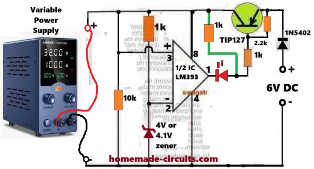
Connect a 1k temporary resistor between pin#8 of the IC and the anode of the red LED.
Keep the supply at zero volts and gradually increase it, until it reaches above 4.1V, or 4V.
At around 3V, you must see the LED turning ON.
Keep increasing the variable power supply voltage until it is above 4V or 4.1V. At this point you must see the LED shutting off.
That's all, this will prove that you LM393 based auto cut off is working correctly.
Now you can remove the above mentioned temporary resistor, and start charging any discharged 3.7V Li-ion battery using the normal configuration, as depicted in the above image.
Constant Current Version
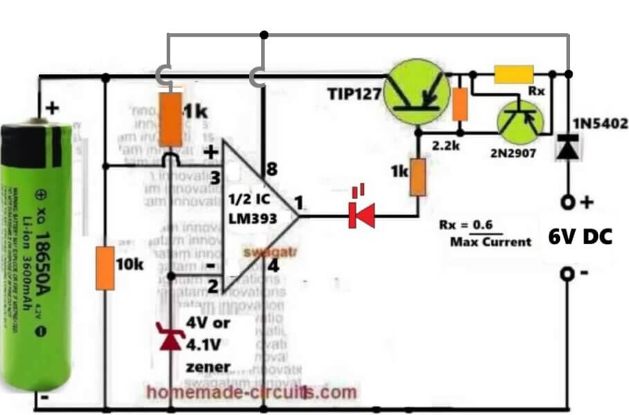
The above circuit can be further upgraded into a constant current version, as shown in the following diagram:
3.7V Auto Cut-off Circuit using IC 741
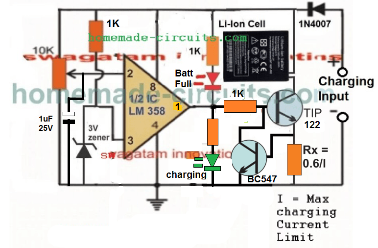
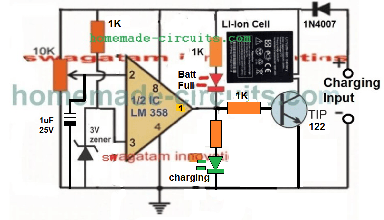
The following IC 741 auto cut off Li-ion battery charger circuit can be understood with the help of the following description:
The IC LM358 is configured as a comparator. The IC LM741 is not used since it is not specified to work with voltages lower than 4.5V.
Pin#2 which is the inverting input of the IC is used as the sensing pin and is attached with a preset for the required adjustments and setting.
Pin#3 which is the non-inverting input of the opamps is reference at 3V by clamping it with a 3V zener diode.
A couple of LEDs can be seen wired across the output pin of the opamp, for detecting and indicating the charging condition of the circuit. Green LED indicates the battery is being charged while the red illuminates as soon as the battery is fully charged, and supply is cut off to the battery.
How to Charge using USB Port
Please remember that the charging process can be quite slow and may take many hours, because the current from USB of a computer is normally very low and may range between 200 mA to 500 mA depending on which number port is used for the purpose.
Once the circuit is assembled and set up, the below shown design can be used for charging any spare Li-Ion Battery through the USB port.
First connect the battery across the indicated points, and then plug in the USB connector with your computer's USB socket. The green LED should instant become ON indicating the battery is being charged.
You can attach a voltmeter across the battery to monitor its charging, and check whether the circuit cuts off the supply correctly or not at the specified limit.
Since the current from a computer USB can be quite less, the current control stage can be ignored and the above design can be much simplified as shown below:
Video Clip showing the automatic cut off action, when the Li-Ion cell is charged upto 4.11V:
Please note that the circuit will not initiate charging unless a battery is connected prior to power switch ON, therefore please connect the battery first before connecting it to a 5 V supply source.
An LM358 has two opamps which means one opamp is wasted here and remains unused, therefore LM321 may be tried instead to avoid the presence of an idle unused opamp.
How to Set up the above 3.7 V Li-ion Charger Circuit:
That's extremely easy to implement.
- First, make sure the preset is moved at the ground side fully. Meaning, the pin#2 should be at ground level through the preset initially.
- Next, without any battery connected, apply an exact 4.2 V across the +/- supply lines of the circuit, through an accurate adjustable power supply.
- You will see the green LED coming ON instantly.
- Now, slowly rotate the preset, until the green LED just shuts OFF, and the RED LED switches ON.
- That's all! The circuit is now all set to cut off at 4.2 V when the actual Li-Ion cell reaches this level.
- For the final testing, connect a discharged battery to the shown position, plug-in the input power through a 5 V source, and have fun watching the cell getting charged and cut-off at the stipulated 4.2 V threshold.
Constant Current CC Feature Added
As can be seen , a constant current feature has been added by integrating the BC547 stage with base of the main BJT.
Here the Rx resistor determines the current sensing resistor, and in case the maximum current limit is reached, the potential drop developed across this resistor quickly triggers the BC547, which grounds the base of the driver BJT, shutting down its conduction and charging of the battery.
Now, this action keeps oscillating at the current limit threshold, enabling the required constant current, CC controlled charging for the connected Li-ion battery.
Current Limiting not Required for USB Power
Although a current limiting facility is shown, this may not be required when the circuit is used with an USB since the USB already is quite low with current and adding a limiter may be useless.
The current limiter should be used only when the source current is substantially high, such as from a solar anel or from another battery
Improving the Circuit Further
After some testing it appeared that the Darlington transistor was unable to switch sufficient current to a Li-Ion cells, especially which were deeply discharged. This resulted in a difference in voltage levels across the cell, and across the supply rails of the circuit.
To combat this issue, I tried to improve the design further, by replacing the single Darlington BJT with a pair of NPN/PNP network, as given below:
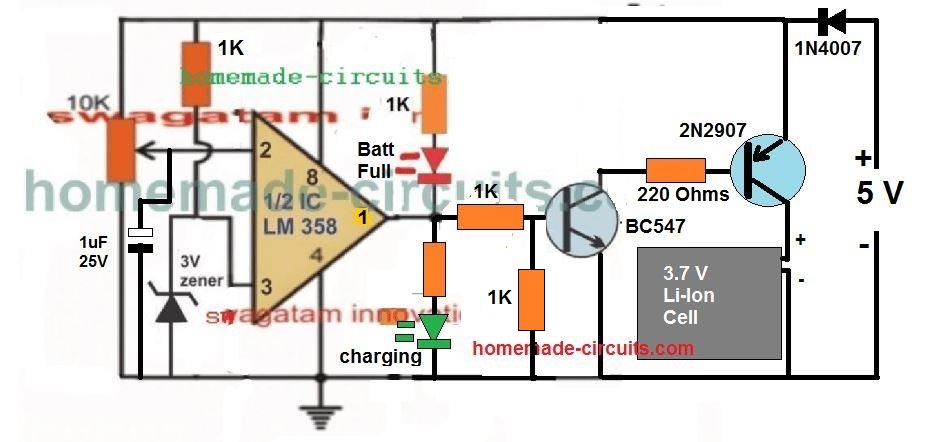
This design improved the current delivery significantly, and resulted in a reduction in the margin of difference between the battery terminal voltage level and the actual supply voltage level, and therefore false cut-off switching.
The following video, shows the test result using the above circuit:
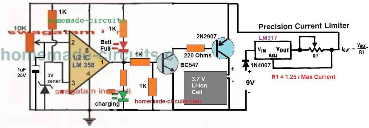
Adding Current Control to the above Design
Using a 5V Relay
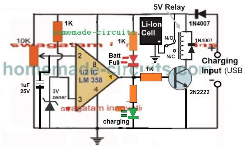
The above designs can be also built using a 5V, which will ensure the best possible current delivery to the cell and faster charging. The circuit diagram can be seen below:
Please Note:
This article was substantially changed recently and therefore the older comment discussions may not match with the circuit diagram shown in this present updated design and explanation.
Another Ideal 3.7 V Battery Charger Circuit with Auto Cut-off
Here's a 3.7 V Battery charger circuit which looks perfect in for the automatic cut-off and a self-monitoring of the 3.7 V battery.
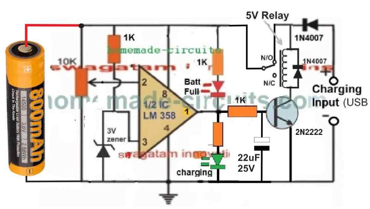
In the relay based circuit previous to the above design, there seems to a serious drawback.
In the previous design the battery needs to be connected first, before applying the input power. This is crucial, otherwise the relay can start chattering, if the power is switched ON first without a battery connected.
But in the above new design where the battery can be seen connected on the left side, the chattering of relay problem is completely eliminated.
Moreover, this design has an added advantage. The circuit will be able to continuously monitor the battery level and self-regulate the circuit to ensure that the battery is automatically disconnected when it reaches full charge level, and automatically connected to the supply when it is discharged to some lower level.
The input supply can can be from any 5V regulated source. However make sure the current spec of the supply is restricted to 0.5 C. Meaning the current of the 5V source must not be 50% of the battery mAh value.
How to Adjust the Preset
The auto cut off preset setting up is easy.
Initially, do not connect any battery or the input supply, and rotate the preset wiper to the ground level.
Next, take a variable DC power supply. Adjust its output to precisely 4.1 V, which is the optimum full charge level of a standard 3.7 V battery.
Connect this supply to the circuit from the left side, across the points where the battery is supposed to be connected.
You will see the GREEN LED illuminating. At this stage the relay must switch ON, however it won't since there's no 5V supply from the right side of the circuit. No worries, we can still setup the circuit by looking at the LEDs.
After this, slowly adjust the preset until the GREEN LED just switches off and the RED LED just switches ON.
That's all, the auto cut off set up is complete for the circuit.
Now, to test the circuit LIVE, you can connect a discharged 3.7V cell across the indicated points, and a 5 V supply from the relay side and see the actually cut-off happening, as soon as the battery is fully charged at 4.1 V.


Questions & Answers
Please sir, i have three questions about the above circuit. When this circuit is charging the cellphone battery, will the LED be flashing? Or is it only when the battery is full that it starts flashing? Secondly, what is the required input voltage and current of this circuit? And finally, what is its output voltage and current?
Hello J-boy,
As mentioned in the article the LED will be lit continuously (solid) while the cell is being charged and will start flashing when the cell is fully charged.
Input should be 5V fixed, you can use a LM317 circuit at the input for allowing higher voltages.
You can remove the 22k resistor entirely for getting a good flashing effect at the full charge threshold.
output voltage will be around 4.4V, current 200mA max
Thanks alot sir. I am grateful. Please sir i sent you an email at "hitman2008@live.in"
thanks j-boy,
sharing phone no wouldn't be possible, I think this is what you had requested in the mail.
We can chat here freely.
Ok. No problems. Please sir, i have a nokia charger(China made charger) that can produce 5.5v and 800ma. Can i use this charger to charge a 6v, 4.5Ah rechargeable battery? If yes, for how many hours can it charge it at a full rate?
J-boy, no you cannot charge with a lower voltage source, you will need a 7V input for charging a 6V batt.
What if i connect a Dickson charge pump voltage doubler at the output of the charger so that it can produce two times the voltage(ie 11v) and then i will use a voltage divider network to reduce the 11v to 7v, will it work normal? Or better still i will use LM317T to reduce the 11v to 7v
It should be able to produce the required charging current also, which should be about 1/10th of the battery AH, then it could work
hello everybody
I have 12v 7.2A battery and I wanna charge my phone via usb port without using computer
I have an usb cable and want to use it in this project
how can I charge my phone directly from this battery please ??
use a 7805 IC for dropping the 12V to 5V, then feed the 5v to the cellphone via the above circuit
..the 7805 will require a heatsink.
thanks so much 🙂
hello Swagatam
would you check this circuit please ??
imageshack.com/a/img30/8392/pgcl.jpg
my phone doesn't recognize it although I test the out voltage is 5.07 !!!
Ok. Thank you sir! Let me try and see what the current will be like
Hi sir,
the circuit is a reliable one ie charges to 100%? No exceptions in i/p current ? i/p v is 5…. can be used for any ampereage li ion batt?
Hi Rohith,
any amperage can be used provided the input also is capable of supplying that much of current and the resistor is correctly calculated.
As i/p v is fixed to 5v i hope i can use 7805s ckt with just ic , diode, 2 caps without current limiting Resistor?? as that of DC to DC charger & provide it to this..??
if the li-ion is within 1ah and 2 ah a 7805 can be used and without the current limiting stage.
Also iam having two types of batt 3.7v & 3.6v (digi cam) li ion. can i charge ? mA may be different for both.
sir i have sent a mail regarding the substitutes for C & R in emergency lamp, havent got any reply… plz check…
you can charge any battery by using the above circuit, but the current limiting should be set appropriately.
Which emergency light are you referring to, is it from this blog?
Sir not from this blog, iam having a 6v 4ah emergency , in which the capacitor was gone firstly (2.2mF 250v) & i replaced, the result was an explosion ,by mistake i took an electrolytic one…. 8ohm 5w R was burned too. now i got a non electrolytic one(0.24mFJ 800v 1200v.dc 50khz) instead of 8ohm R i got 10 ohm 5w can i use it safely….???
yes 0.24uF/800v will work but will not charge the 6v/4ah battery. 10 ohm will do for 8 ohms
by the way i have answered your email.
Please sir, i could'nt get the uA741 8-pin op-amp. Can i replace it with LM358 or LM324 by using one of its op-amp train, since, the 358 is a dual op-amp, while 324 is quad nand op-amp?
Yes you can do it, no issues.
so what can i opt for?? sir y it doesnt charge ? plz explain…..
use a 0-6V transformer power supply with a bridge rectifier and 2200uF/25V filter capacitor, capacitive power supply will not work
sir i have charged that way, its been charging quite ok… but actually on that emergency ckt board a capacitor & resistor & some others were present , in which two things gone C & R their original values i have told u & u said 10ohm is ok but any other substitutes for C ?
Sir as a beginner i would like to know what is a capacitive power supply?
also why cant it be used for lead acid battery?
Thanks in advance…
Rohith, please refer to the first diagram in this article, you should do it in this way:
https://www.homemade-circuits.com/2011/12/how-to-make-efficient-led-emergency.html
capapcitive power supplies produce lower currents and higher voltages,both are not suitable for lead acid batteries.
please sir, can i use only resistor to drive a 1 watt white LED from an AC source? If yes, what should be the resistance of the resistor and if no, what should i include in it?
330 – 3.3/.3 = 1089 ohms or a 1k resistor will work
wattage will be around 100 watts.
it's better to use a cell phone charger instead., you can use a 3 ohm/2watt resistor with it
Hi sir. Thanks for helping me with the last project.
Now I was considering another project . Actually I want to make a "18650" cell charger.
Could you help me in making one?
Hi Anirudh,
please provide more details about the project.
Sir..actually I have some laptop batteries….from which I have spared the 18650 cells that are present inside the battery.
I use the 18650 for many battery operated projects….but I dun have any way to recharge them..
Don't have much money to buy one from market…so I thought of asking u to please help me in the making of a 18650, 3.7 volts cell charger.
Anirudh, you can try the circuit that's shown in the above article, it will suit your application.
Thanks a lot sir.
And I also wanted to confirm..I need 4.2 volts and 1 amp from the charging circuit. Will it deliver so? ( I have the 5v 2 amp input for the charging circuit input).
Suggest me if any change required sir.
for 1amp output replace the 3 ohm resistor with a 0.6 ohms, 1 watt resistor, rest will be as is.
Thanks a lot sir. Your replies have always been abrupt. 🙂
Thanks for guiding.
Sir. We tried assemble your circuit but even the led is not turned on. Do you have any tips on how should we troubleshoot the circuit?
Turning the preset to and fro should cause the LED to switch ON/OFF at some specific point on the preset, if this is not happening means there's something incorrect in your circuit connections.
Dear Sir,
Manu thanks to you for this circuit. I have one question sir. I think you have used the OP-AMP as Schmitt Trigger. But one thing I didn't understand for the LED to blink, terminal 3 of the OP-AMP should go above 1.8V and for that to happen current through the 10k pot. should rise. So, my question is will the current through the Li-ion battery drop automatically increaing the current through the 10k pot?
Dear Kallol,
The voltage at pin3 will drop and will be below the reference level at pin2 while the discharged battery is being charged.
This will create a low at pin6 which will keep the LEd and the PNP latched ON for supplying the charging voltage to the batt.
As the batt becomes fully charged, pin3 voltage will rise and at some of time cross pin2 potential, reverting the pin6 output to high, switching off the PNP and the charging voltage.
My heartiest thanks to you sir.
you are welcome!
Sir, what is the function of 10k variable resistor in this circuit?
It's for setting the full charge cut-off level of the battery.
how to set it??
Since I am making a power bank, will you upload a circuit schematic of dc-dc booster? which will convert 3.7v li-on battery to 5v or greater (I will use 7805 to make it 5v) and output current of 2a
sir, usb negative and ground wire in this circuit are separate??