• Skip to main content
  • Skip to primary sidebar

Homemade Circuit Projects

Need circuit help? Post them in the comments! I've answered over 50,000!

Blog | Categories | About | Hire Me | Contact | Calculators-online
You are here: Home / Security and Alarm / 2 Tone Ringtone Generator Circuit


2 Tone Ringtone Generator Circuit

Last Updated on January 19, 2025 by Swagatam 4 Comments

The IC LS1240A from SGS Thompson is specifically designed for generating a 2 tone ringtone generator circuit. Thus the IC specifically becomes suitable for landline telephones for producing the ringtones when a call is received.

Table of Contents
  • Technical Specifications
    • Pinout Details of the IC LS1240 dual tone generator IC
      • Circuit Diagram of two tone music generator using IC LS1240
    • Two Tone Generator using piezo element

However with little modifications the IC can be easily utilized for normal applications, in circuits where a double tone alarm may be required.

Technical Specifications

Basically the IC is a 8-pin DIL chip resembling the IC 555 and has the following specs:

  • Very low current consumption yet good audible response at the output.
  • Internal built-in rectifier stage for rectifying an AC input supply, a filter capacitor is also a built-in feature of the IC.
  • Hardly any external components required for setting up the circuit.
  • The tone of the output musical audio can be adjusted externally through a resistor.
  • If the IC os used inside a landline telephone then the supply to the IC is derived from the line voltage via a 1uF capacitor.
  • The IC is able to drive a piezo electric transducer directly without the need of inductors or amplifiers.
  • The IC is also capable of driving a small loudspeaker directly for generating the musical output.
  • However the speaker must be rated at minimum of 50 Ohms.
  • The following 2 tone ringtone generator circuit shows how to configure the IC LS1240 as a two tone musical signal generator circuit.

Pinout Details of the IC LS1240 dual tone generator IC
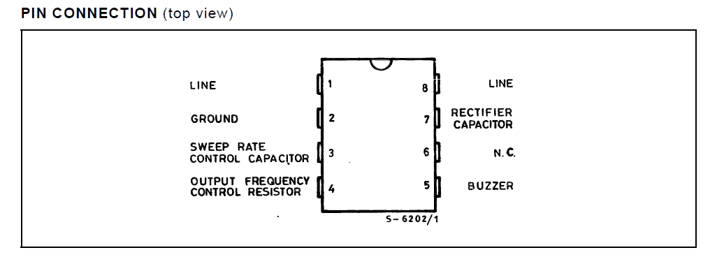
Pinout Details of the IC LS1240 dual tone generator IC

Circuit Diagram of two tone music generator using IC LS1240
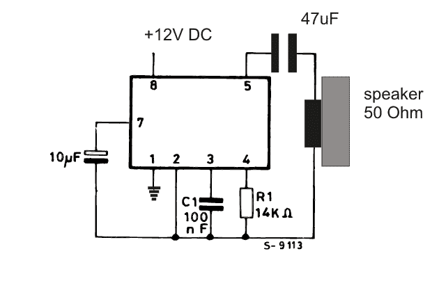
Circuit Diagram of two tone music generator using IC LS1240

Two Tone Generator using piezo element
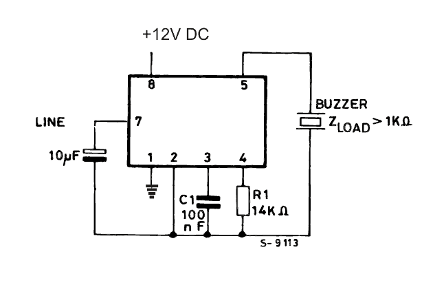
Circuit Diagram of two tone music generator using IC LS1240 and piezo element

Courtesy:

You'll also like:

  • Mobile Phone Controlled Door Lock Circuit
  • Make this Simple Refrigerator Door Open Alarm Circuit
  • P 20161027 182018 1 p 1RFID Security Lock Circuit – Full Program Code and Testing Details
  • IRdoorlockcircuitInfrared Remote Controlled Door Lock Circuit

Filed Under: Security and Alarm Tagged With: Generator, Ringtone, Tone

About Swagatam

I am an electronics engineer and doing practical hands-on work from more than 15 years now. Building real circuits, testing them and also making PCB layouts by myself. I really love doing all these things like inventing something new, designing electronics and also helping other people like hobby guys who want to make their own cool circuits at home.

And that is the main reason why I started this website homemade-circuits.com, to share different types of circuit ideas..

If you are having any kind of doubt or question related to circuits then just write down your question in the comment box below, I am like always checking, so I guarantee I will reply you for sure!


Previous Post: « 2N3904 Datasheet [40V, 200 mA NPN Transistor]
Next Post: Timer based Water Level Controller Circuit »

Reader Interactions

Questions & Answers

Total Posts: 4
Newest Oldest
Kit Jamieson
December 5, 2019 • 7 years ago #72810

Dear Swagatam,
I am trying to find a circuit with which to build an accurate stable two frequency AC signal generator.
The two frequencies I require are 528Hz and 1/13th harmonic of 40.6Hz which I then need to push through an amplifier circuit to achieve a minimum of 200 ohms.
The voltage input would ideally be 15volt DC, which I wish to switch via an existing frequency generator with a Photomos gate.
This would hopefully give me a 50:50 528Hz/40.6Hz AC signal output to an amp. switched via the Photomos gate also opening and closing at 528Hz.
The original circuit is accurate to 3 decimal places.
Can you help, please?
Thank you so much,

Reply
SwagatamAdmin
December 6, 2019 • 7 years ago #72820

Dear Kit, I am sorry, I have no idea how this can be implemented?

Reply
Anil Kumar.K
November 24, 2017 • 9 years ago #56093

Dear Swagatham
I assembled this circuit. There is no sound, from speaker/ ceramic transducer.
My experiments :-
1) I tried two LS1240A ICs removed from two landphones.
2) I tried speaker ( 2x30ohms speakers in series.
3) I used same piezo ceramic transducer (without inbuilt oscillator) from the landphone.
4) I tested with 9vdc to 17vdc.
5) I shorted pin 1 (LINE) to pin 2 (Negative).
Why there is no output….? Does this circuit need AC voltage at pin1 and pin 8….? If yes what should be the minimum and maximum AC voltage range….?

Regards

Reply
SwagatamAdmin
November 25, 2017 • 9 years ago #56097

Dear Annil,

the IC has an internal rectifier circuit so it does not matter whether the input is an AC or DC, it should work with both.
However the IC has only one negative pin at pin#1, no other point in the circuit is connected with the negative supply, so I hope you have connected this correctly.

I think your IC may be faulty, you can further confirm the circuit by using a headphone instead of the speaker.

Reply

Need Help? Please Leave a Comment! We value your input—Kindly keep it relevant to the above topic! Cancel reply

Your email address will not be published. Required fields are marked *

Primary Sidebar

My YouTube Channel

Circuit Simulator: Draw and Simulate Schematics

circuit simulator image


Categories

  • Arduino Projects (95)
  • Audio and Amplifier Projects (134)
  • Automation Projects (18)
  • Automobile Electronics (104)
  • Battery Charger Circuits (90)
  • Datasheets and Components (109)
  • Electronics Theory (151)
  • Energy from Magnets and Earth (43)
  • Games and Sports Projects (11)
  • Grid and 3-Phase (20)
  • Health related Projects (27)
  • Home Electrical Circuits (13)
  • Indicator Circuits (16)
  • Inverter Circuits (98)
  • Lamps and Lights (161)
  • Meters and Testers (72)
  • Mini Projects (28)
  • Motor Controller (68)
  • Oscillator Circuits (30)
  • Pets and Pests (15)
  • Power Supply Circuits (91)
  • Remote Control Circuits (50)
  • Security and Alarm (65)
  • Sensors and Detectors (107)
  • SMPS and Converters (46)
  • Solar Controller Circuits (62)
  • Temperature Controllers (44)
  • Timer and Delay Relay (51)
  • Voltage Control and Protection (44)
  • Water Controller (37)
  • Wireless Circuits (31)


Subscribe to get New Circuits in your Email


Other Links

  • Privacy Policy
  • Cookie Policy
  • Disclaimer
  • Copyright
  • Videos
  • Sitemap

People also Search

555 Circuits | 741 Circuits | LM324 Circuits | LM338 Circuits | 4017 Circuits | Ultrasonic Projects | SMPS Projects | Christmas Projects | MOSFETs | Radio Circuits | Laser Circuits | PIR Projects |


Recent Comments

  • Swagatam on Adjustable Voltage Regulator Circuit using LM324 IC with Over Current Protection
  • Swagatam on Inverter Circuit with Feedback Control
  • Swagatam on Inverter Circuit with Feedback Control
  • Swagatam on Proximity Detector IC CS209A Pinouts – Datasheet Explained
  • PRAFUL WANDHARE on Proximity Detector IC CS209A Pinouts – Datasheet Explained

Social Profiles

  • Twitter
  • YouTube
  • Instagram
  • Pinterest
  • My Facebook-Page
  • Stack Exchange
  • Linkedin

Calculators

  • ZVS Induction Heater + Tank Calculator Tool
  • Zener Diode Calculator
  • Wire Current and Thickness Calculator (Ampacity Calculator)
  • Voltage Divider Calculator
  • Transistor Base Resistor Calculator
  • Transistor Astable Multivibrator Calculator
  • TL431 Calculator
  • Solar Panel, Inverter, Battery Calculator
  • Ferrite Core Air Gap Calculator Tool
  • Parallel MOSFET Calculator Tool: How to Connect MOSFETs in Parallel Safely
  • LC Resonance Calculator for EV Battery Charger Circuits
  • LED String Series Resistor Calculator
  • PFC (Power Factor Correction) Calculator Tool: 3kW
  • Passive Power Factor Correction (PFC) Calculator
  • LM567 IC Calculator Tool
  • SMPS Flyback Boost Converter Calculator
  • Shunt Resistor Calculator for Ammeters
  • SCR and Triac Gate Resistor Calculator
  • Battery Back up Time Calculator
  • Boost Converter Calculator (Non-Isolated)
  • Bootstrap Capacitor Calculator
  • Buck Converter Calculator
  • Buck-Boost Converter Calculator
  • Capacitance Reactance Calculator
  • DCM Flyback Transformer & Wire Gauge Wire Size Calculator Tool
  • Filter Capacitor Calculator
  • IC 4047 Calculator (Frequency and PWM)
  • IC 4060 Calculator
  • IC 555 Astable Calculator
  • IC 555 Monostable Calculator
  • IC SG3525, SG3524 Calculator
  • Inductance Calculator
  • Induction Heater Inductor and Resonant Frequency Calculator
  • Induction Heater Work Coil Calculator
  • Inverter LC Filter Calculator
  • LC Resonance Calculator
  • LED Current Calculator
  • LM317, LM338, LM396 Calculator
  • NAND/NOT Gate RC Values Calculator
  • NOT, NAND Gate Frequency Calculator
  • Notch Filter Calculator Tool
  • Ohm’s Law Calculator
  • Phase Angle Phase Shift Calculator
  • Power Factor (PF) Calculator
  • RC Filter Calculator
  • Reactance Calculator
  • Sine Table Calculator for SPWM Arduino Code
  • Small Signal Transistor(BJT) and Diode Quick Datasheet
  • SMPS Calculator for Toroidal Ferrite Transformers
  • SMPS Flyback Transformer Calculator – Design by Target Duty Cycle
  • TL431 Calculator
  • Op-Amp Hysteresis Resistor Calculator

© 2026 · Swagatam Innovations