Grid-tie inverter concepts may appear to be complex due to the many criticalities involved with them, however with some intelligent thinking it could be actually implemented using primitive technologies. One of the ideas has been explored here.
Introduction
The discussed idea of a simple grid-tie inverter circuit was suggested by one of the interested readers of this blog, Mr. RTO.
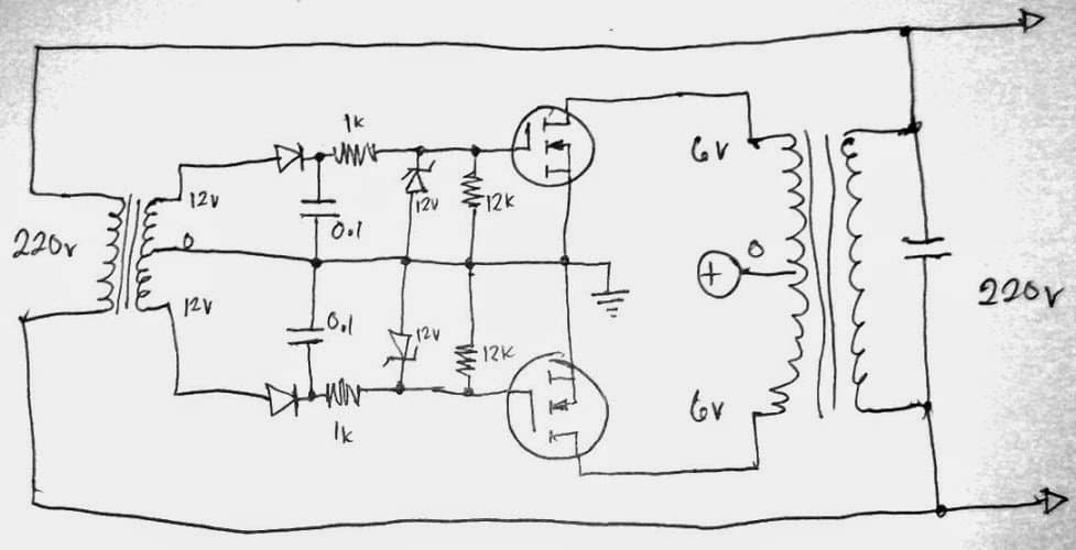
The images sent by him are shown below. In the first image we find the simple circuit diagram comprising a step down transformer for translating the grid data, a mosfet triggering circuit which accepts the grid data and a corresponding inverter transformer which is used to amplify the DC conversion of the grid data from the mosfet network.
A Smart Looking GTI Circuit
The idea looks pretty simple, and indeed very smart:
The left side step down transformer feeds the half wave rectified voltage to the corresponding mosfets which begin conducting in-sync with the grid input and convert the DC source into a corresponding AC across the inverter transformer at the right hand side. The output from the inverter transformer which is now a grid synchronized AC feeds the grid with the intended GTI results.
The idea has been tested by Mr RTO, but he complains about lower efficiency from the unit.
This could be because of one major issue in the design, that is the absence of a "neutral" wire across the output of the inverter transformer.
With the shown set-up, the output would respond with a push-pull action across the secondary of the right hand transformer, meaning both the ends would become "HOT" or "LIVE" alternately during the operations.
The grid will take this as a "short" for every inverted half cycle from the transformer, because the grid voltage always has one wire as the neutral which is never a "LIVE" terminal.
We don't want this to happen.
Using a Center Transformer
A simple solution is to use a center tap winding for the secondary of the inverter transformer. This would render the center as the "dead" or "neutral" wire relative to the outer taps of the trafo. The upper tap may be configured with the grid while the lower tap to a balancing load or more effectively fed back to the primary side for charging the battery or reinforcing the DC source itself.
Warning: The author cannot be held responsible for the results of the experiment. Please do it at your own risk!! The projects explained here are recommended only for the experts in the field of electronics.
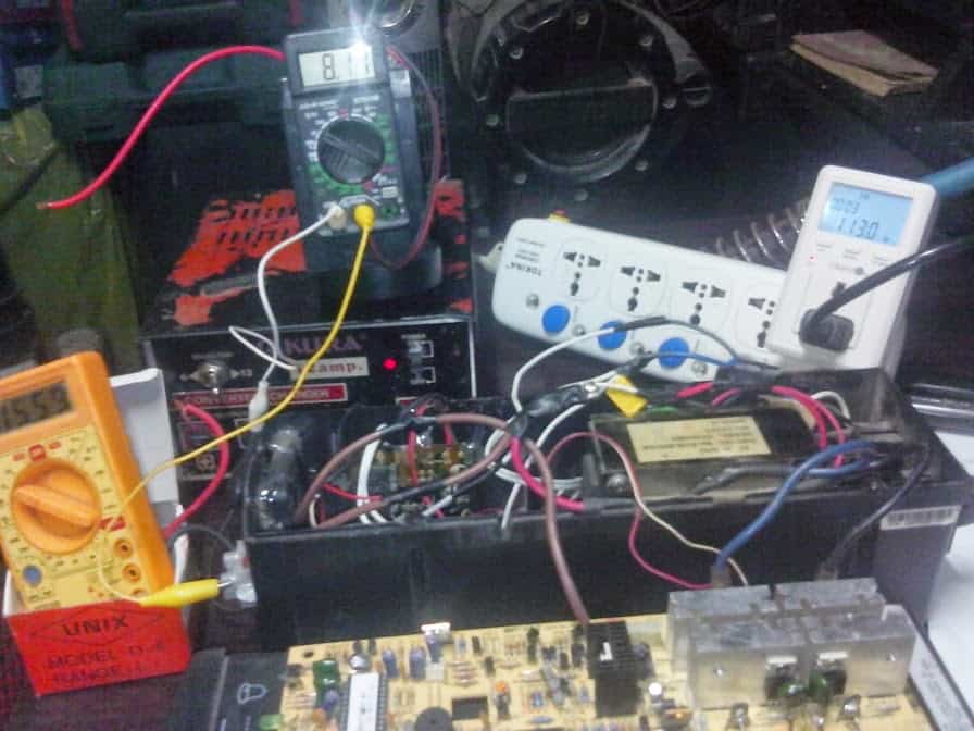
The test set-up of the above design can be witnessed here:
Another issue which could remotely transpire is the conduction from the mosfet which wouldn't be exponential, rather an "awkward" and unrecognizable sinewave.
The mosfets could be replaced with SCRs, as shown below. This would allow a perfect sine wave to be induced across the inverter transformer and the grid.
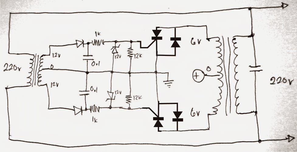
Using SCRs for the GTI
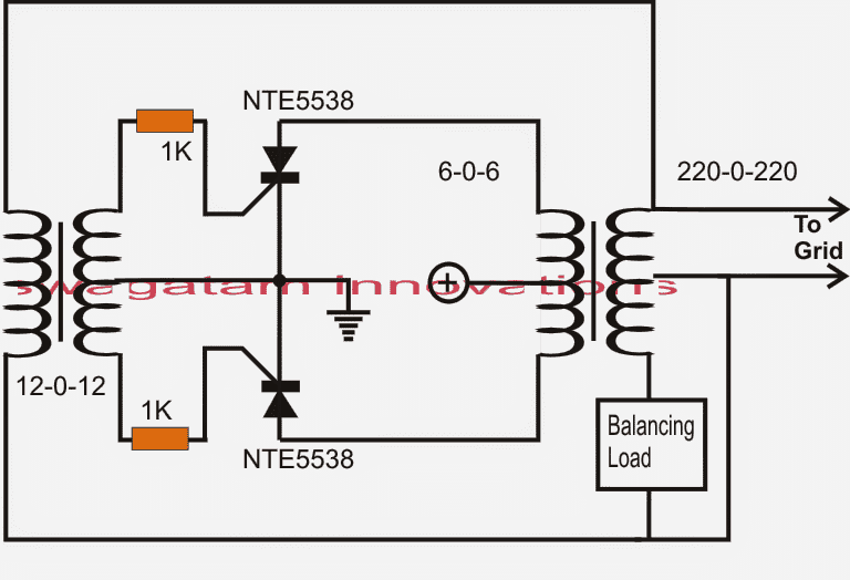
A much improved grid-tie inverter circuit using the above concept and SCRs is shown below. The idea looks greatly simplified, and quite impressive.
The output of the right and transformer could be seen converted to a center tap topology, wherein one half winding is integrated with the grid, while the other half is subjected to a balancing load so that the center tap is appropriately conditioned to be the neutral for the system.
The balancing load could be replaced with a charger circuit for charging the inverter battery itself, this would reinforce the input with additional power and more backup time.
SCRs will not Latch
At first glance it appears that the SCRs would get latched since a DC is being used across its anode/cathode, however according to me it won't happen, because the gate of the SCR is subjected with an alternately reversing AC which would prevent the SCR from getting latched every time the gate AC feed changes its polarity


Questions & Answers
Hello! The signal transformer (that on the left) gives you a phaseshift. In my opinion – there needs something like PLL (CD4046) and MOSFETS – the efficiency and reliability will be better. There you should give an impulse after zero cross point and moreover have enough hold current. Perhaps a 555 timer can help in this situation?
Hi, I think the transformer based design as shown above is perfectly synchronized with the grid AC and is extremely rugged, so it seems to be more reliable than an electronic version…
Hi
Is the final circuit applicable?
is it need any extra part ?
The design it not practically tested, if you have understood the concept well, then you can try it.
Hello Mr.Swagatam, I’m Brazilian and I really like electronics, I even like to study and build your projects. Your posts are really good!
I currently have some solar panels and I intend to assemble and use the circuit described above, my question is: should I directly use the energy from the solar panels or use the battery to power the mosfets?
Hi Davi, thanks you and glad you liked my projects.
You can use the solar panel directly as the DC for the inverter, but make sure the voltage from the panel is controlled and not high for the inverter
Hello Mr. Swagatam, thank you for answering my questions soon, understood, regarding the dc power supply from the panels to the inverter, the control can be done by transistors such as Tip 35 or similar, scaling the desired current through several transistors.
I’ll test it and then I’ll comment on my results.
Hello Davi, yes the solar panel voltage can be controlled through transistors.
Ok, thanks!
The other question is: About the transformer with central tap at the output, can I simply connect one of the phases to the grid and a capacitor to the other phase?
Please clarify my reasoning! Thank you!
Actually I am slightly confused with the connections with the center tap output, I am not sure how to address the neutral line of the grid. At the moment I cannot provide any suggestions.
Hello!
I tested
There is a lot of energy lost in the system.
Do you have a solution?
Hi, Please disconnect the 220V side of the inverter from the grid and check again! Check whether it is still heating up or not?
Sir,
Thank you for this schematics.
According to what I understand, if battery voltage is above transformer ‘low voltage’ side, circuit acts as a generator to the grid. Anyway I have few questions to understand well :
1) What about power send to the grid : if I have a 300VA transformer, will it be always around 300VA (minus deperditions) ?
2) What if grid voltage increase (or battery voltage decrease) so transformer low voltage side goes higher than battery voltage ? How does this circuit acts ? Does it stop injecting current to grid or it start to ‘charge’ battery ?
Hi Pierre, yes the automatic pWm control will make sure the inverter output is always constant, and its voltage level is equal to the grid voltage. The inverter is used for assisting the existing grid supply so the inverter transformer can be never overloaded.
the PWM control is with resepect to the grid voltage, so if the grid voltage increases or decreases the inverter voltage will also correspondingly increase and decrease.
hi dear master
Please put the pure sine wave sample using the Darlington Couple tip35 and Tip122
best regards
Muhammad, which circuit are you referring to?
in the following
To replace the mosfets in the circuit with the Darlington Couple
OK, you can do it, first try with single Darlington devices such TIP142, if it works then you can replace it with TIP122/TIP35 pairs.
first of all thanks for response
combining of first diagram in this article and below link , plz
https://www.homemade-circuits.com/upgrading-low-power-inverter-to-high.
Good day Mr. Swagatam. Is it possible to grid tie connect to the ac output of pure sine wave inverter? I want to add power to my existing solar system in this case a 1kW PSW inverter using 1kW GTI. The reason I want to connect it that way because my electric meter will add my solar generation if I connect the GTI to the grid. Other solution to this is with the use of limiter. Is my idea for PSW inverter being grid tied possible or doomed for failure?
Good day Roel, it may be possible only if your sine inverter is specifically designed for a GTI integration, if it is a normal inverter then I won’t recommend this at all. So make sure the inverter includes the synchronization feature with the grid sine waveform and only then you may be able to use it as a GTI
Good day Mr. Swagatam. What I mean is that I had an existing off grid solar inverter with 1000W pure sine and I want to add more power using another solar but in this case the inverter is 1000W pure sine grid tie type BUT I don’t want it to connect it to the grid but to the AC output of my existing off grid 1000W pure sine inverter. Is this possible?
Ok so you mean to say you want to join two 1000W inverter outputs in parallel? I think that may not be recommended, because their waveforms could be out of phase and cause catastrophic results, I personally won’t recommend that! I hope I understood your issue correctly?
Yes Sir Swagatam it seems that the two inverters are to be connected parallel because that’s the only way to connect the grid tie inverter and I think grid tie inverter will automatically sync the grid requirement but my concern to this idea is during a moment where the load is lower compare to the capacity of the grid tie inverter which in this case will throw that extra power back to the ordinary inverter. And I know and think that there is going to be a fight of power in that case whoever is the strongest wins. I only need to confirm through your broad knowledge of inverter circuits if this is so. I heard some idea also that the extra power generated by the grid tie inverter and will flow towards the ordinary inverter will charge the battery of that ordinary inverter. Thanks by the way Mr. Swagatam to your knowledge and sharing that knowledge to everyone. Your circuit are very simple yet very applicable. Thanks Sir Swagatam.
Hello Roel, When we refer to synchronization, that implies excess power can neither be sent or received from the two sources. When the amplitudes of the grid and the inverter output voltages are in sync, their voltage peaks and cycles become exactly equal and synchronized, and when voltages of two power two sources are exactly similar, transfer of current cannot take place.
Good Morning! for the initial design with the 6v transformer, the batteries would give from 6v or 12v ????
I’m going to ride one of these to play.
sir please send me circuit of phase lock loop or alternate .
if possible I’ll try
ok!
I’ll have to use 12 + 12!
the ideal is not to have a higher voltage than the network?
tks
the trafo can be 6-0-6 or 12-0-12 that’s not crucial….the battery should be equal to the trafo voltage rating..if it is 12-0-12 then batt should be 12V if 6 then 6
Hi, the battery should be also a 6V, rather 7V when fully charged.
Hello mr swagatam
Thank you for answering so quick
I already have the capacitor on the output which makes the square wave perfect .The question now is , can i connect this signal to the grid or i would have a sine wave ? I will try the
trick with the bulb
Hello Thrasos, if the secondary of the transformer is generating voltage equivalent or higher than the grid level then you can try connecting it with the grid. make sure to connect a fuse in series with the mosfet drains or SCR anodes
Hello sir
I tried this disign above and the signal on osciloscope it is not sguare wave or clean sine wave .
I found other design and i have a clean square wave .I can not communicate with the designer.
I was wondering if i have square wave ,as i read above can i connect to the grid ,is this is going to become sine when it will connct to the grid ?
Thank you
Thrasos
Hi Thrasos, as you can see the design does not have any special circuit processor, therefore the output waveform will be solely dependent on the switching pattern of the devices…you can perhaps improve the waveform by adding a 0.33uF/400V capacitor across the output leads of the transformer
Is there any update for this article? I found it very interesting.
thanks, I am glad you liked it, what kind of update are you expecting?
Hi Mr.Swagatam,
I check in datasheet that NTE5538 can hold up to 800 volts and 50 Amperes. So if I have DC source maybe about 600 volt (from a lot of solar cell in series), do I only need change the right side transformer from 6-0-6 to 600-0-600 ? or I also need to upgrade the SCR ?
can I avoid using balancing load in this schema ? it's make the GTI not independent.
thank you
Hi, I think you should try it yourself practically by making small models of the above designs, and verify which one works more efficiently, there are hardly any components in the design and the set up looks quite cheap.
make sure not to connect the output with the grid line while testing the set ups.
Hi i just wany to know which gti cirucit gives the best efficiency.
Because i read a lot of previous posts by barbe israel but he did not clear the confusion about the efficiency of his experiments. Anyone plz clarify if know sonething about it. I am electrical engineer, i want to start with the most optimal design and refine it. So plz help me out.
Regardd
Hammad
6-0-6 transformer will heat up only under the following conditions:
if the mosfets are not oscillating and/or the DC supply to its center tap is much higher than 7V….otherwise there's no reason it can burn.
first test the set up without connecting the 6-0-6 output with the grid.
and if possible change the mosfets with new ones.
My friend is Brazilian and I live in Africa faso volunteer work here I set up the first circuit with mosfet only the transformer 6-0-6 heats up so much and it burns in minutes I do not know where I'm going wrong can give me an idea
to avoid the balancing load…you can try connecting only one wire from the output of the GTI transformer…connect this to the Phase line of the Grid, don't connect the other wire….even this will need some consideration by ensuring that the both the cycles GTI and grid are in sync
Hi Greenmoon,
yes the 6-0-6 winding will need to be upgraded as per the input voltage and should be equal to the input voltage rating.
SCRs also will need to be upgraded as per the input voltage and current specs
help h pridge diagram dc to ac baruti.themigambo@gmail.com
try this
https://www.homemade-circuits.com/2014/01/simplest-full-bridge-inverter-circuit.html
sir can i have a full diagram of dis GTI inverter i want to make one in my slora set up thx…
Rose, Just replace the center tap DC with your solar panel (+), and make sure the transformer rating matches the solar input.
help diagram for h bridge dc to ac
hello swagatam.
is this suitable for high and low voltage dc?. i want to build this one for my diy turbine generator.
how much current it can handle? can it be modefied to produce high power generator?
hello kikiloaw,
sorry it's not designed to work on DC
Hello Thrasos, I am afraid a two wire transformer can never work for the above shown designs,….. where did you feed the DC positive?
The 115V that you might be getting could be something else but not because of the GTI functioning.
PWM feature can be executed by feeding pulses across the gates of the SCRs…we'll discuss it in detail once you correctly and successfully implement the above designs.
Hello Thrasos,
If you are referring to the designs presented in the above articles, then yes these can be used with a 100AH batteries also, you just have to makes sure the power devices are rated accordingly.
However you will strictly require a center tap transformer for making the above explained circuits, I am unable to simulate how a two wire transformer could be configured using the above concepts.
I would recommended that you first try the designs using smaller transformers and a smaller battery, if the mini prototype works as per the expectations only then you may want to go for the bigger models.
yes it's a center tap trafo…0 refers to the center tap voltage of the trafo with respect t0 the outer 12v taps
Hello, I'm from Brazil and I'm using google translator …
Well I wonder if the first circuit presenting can use mosfet IRFZ44N.
In the picture the transformer has a secondary of 6-0-6 because not 12-0-12
hello, yes any suitably rated N mosfet can be used in the mentioned design.
12-0-12 can also be used instead of 6-0-06V trafo
Hi mate…why we start xperimenting water fuel engine????
yes mate, it has been already invented successfully using HHO fuel engines….I don't have much idea of the mechanical stages of the engine, though.
Hi Swag, I made some simulation for mosfet vs scr. I don't if this is right, I get curve line on mosfet and straight line on scr. Please see this link postimg.org/gallery/96dgt9ge/
Hi RTO, may be the simulator was not specified regarding the AC polarity, the AC would be changing polarity alternately at 50Hz rate,
I think you should simulate the last circuit above exactly as it's given
Thanks Swag, this information will help to me.
Btw, how about the gates voltage, if I will give it 2volts vs 5volts. What would be the result? It is the same with mosfet that the more voltage on gates will get less resistance on Drain and Source?
yes, only upto the saturation level, once the Vgs crosses the saturation point which could be at about 6V, the drain/source conduction will tend to reach a constant level
Hi Swag, this is my first time using SCR. According to my research, once the scr triggered it will always ON and the scr will turn off if we disconnect the source voltage. On the circuit diagram above, I can't see how scr goes OFF.
I research again mate with the scr…the issue is the switching on and off..is to complicated circuit to be used if u want scr…i tried again..mate sorry not working…!
whenever some doubtful and critical parameter is required to be confirmed, it must be scaled down proportionately to avoid mishaps, the above concept can be tried using a 1amp 12-0-12V transformer for the inverter transformer. and BT151 may be used for the scrs.
for extra protection fuses may be atached at the scr anodes.
Not sure mate..but my friend here suggest it will possibly working on his theory if we used triac…
It will using optocoupler..it will switch and off..im sure..using 555 to be simple or if you want some noise used relay to switch it off and on very fast…i see that one in action actually its cool if u just want some fun on your gti used relay..but optocupler for the scr is the best..
Hi mate actually..i dont see yet the scr works..just have doubt on it…because i check the scr on the net i dont see a very fast switching which we need on gti…like what happen to me my scr juz blow mate i used high amps..aswell 500/60amps…i waste my 10 dollars mate
Hi RTO,
you are correct, but there's another way of breaking the latch, it's by providing a negative voltage to tge gates, that's what exactly would happen for tge gates of the SCRs shown above.
With every alternating voltage, the transformer taps will change polarity, supplying a negative voltage to tge ScR gates…according to my theory.
For the gti..i would suggest this igbt. Gt30j324 or gt30j322 im sure with this…!!! Take cage with the gate,,,, as always….make sure bout the current flow…like i said a resistor needed..for unstable current…maybe 1 ohms 50 watts will handle….! Series to the positive of the battery or solar…
But my design will activated only when connected to grid…! So at the moment im on trial on switching via relay…to amke more my gti in safe mode…and after one ahour of used my big transfo become hot…but all the igbt in very cool… I thnk i need to search some good ventalation for my transfo…
OK, if you are confident with your assumptions, then there's no problem you can go ahead with your plans.
but according to Wikipedia a GTI should have the following features:
The grid tie inverter must synchronize its frequency with that of the grid (e.g. 50 or 60 Hz) using a local oscillator and limit the voltage to no higher than the grid voltage. A high-quality modern GTI has a fixed unity power factor, which means its output voltage and current are perfectly lined up, and its phase angle is within 1 degree of the AC power grid. The inverter has an on-board computer which will sense the current AC grid waveform, and output a voltage to correspond with the grid. However, supplying reactive power to the grid might be necessary to keep the voltage in the local grid inside allowed limitations. Otherwise, in a grid segment with considerable power from renewable sources voltage levels might rise too much at times of high production, i.e. around noon.
Also have nothing much knowledge on gti so i deside base on suggestion and help on others and share aswell to everyone…he told me gti is build to give extra to your grid…the more you put the more the wattmeter reverse…or slow when using ac..i really dont understand… But being compuse..i see that my wattmeter reverse..quick…with no shake hand….no pwm…nothing..just simple inductive circuit..he just told me bout if your circuit is purely capacitive or inductive no current used….but hence he said i generate…more the wattmeter no choise but to reverse..which actually work..same on wat i made…!!! I need xplaination here mte…that little crazy qwxdx…made me mad..for some kind…but he made it…
I did as usual touch it by my hand… The line that i believe its neutral..and like u sugest insted i used meter…zero mate the reading and no elctrc shock…i can confirm its all harmonic only…nothing more….and when you put filter neutral became zero….
Thats wat i found….
Sorry Mate, but your inverter doesn't need to fight the grid, that's horrible, rather you have to make sure your inverter output "shakes hands" with the grid output, that's why it's so important to have everything in order.
for confirming whether your inverter output has a neutral or not you can do the following simple steps.
take a 25 watt bulb, connect one of its ends to one of the taps of the inverter output, connect the other end of the bulb to your home earthing or to any water tap.
Switch ON the inverter, check if the bulb glows or not,of course it'll glow.
repeat the procedure for the other tap of the invetter output, check the results.
You'll find that the bulb glows on both the occasions, proving that both the ends of your inverter are producing "LIVE" voltages…..that could be very undesirable for a grid integration.
Hi mate..base on my research and friends aswell we should not worry bout the voltage we get from neutral on gti…is just actually some kind of harmonic..static but no current at all..that is why when i touch it nothing happen…
My friend told me which he have lot of knowledge on gti..he said just make sure build a lot of wattage to fight with the grid…and make your meter reverse…i will ask him a more solid xplanation on gti..but most of his gti design was not actually much or tie with grid but is working and effeciency is high like 90 to 95 percent…!
OK mate, that's fine.
The inverter output must be an exact replication of the grid AC.
The grid AC has a neutral which is never LIVE, the same should be obtained from the inverter output, that's why I am suggesting on having a center tap at the output.
Mate not too hot…is actually normal….kind of hot…but im thinking im going to use this one 24hrs..im sure..it will be hot…so need some air on the transfo same on the gti i both online…
Im not using center top…i found some dificulties with center top…when i look into scope it is hard to align the movement…i dont really understand…coz i really not focus to trouble shoot that thing…so i made it no center top much easy…and perfect..
Anyway i will look that one and try but so far without center top i found the waveform perfect…and no noise or interfernce…very nice square wave also compare with the center top the square wave is not smooth..and frequency somtimes become 600 to 10 khz while without center top..stable at 90hz or 80 hz juz put the caps boom 49 to 51hz..clean squarewave and when u put to the grid automatic very neat sinewave…compare again with the center top…you need to clean the power factor…mate u will not be happy if u see to mch scratch on sine wave..and after 5mins your igbt become too hot and transfo…
IGBT gate is voltage dependent just like mosfets.
mate the transformer too should not become hot..I suggested the use of a center tap configuration at the output, did you do it?
before carrying out critical and dangerous projects like this one we should be very sound with the required info and knowledge, especially the basics, otherwise it could lead to hazardous situations….
Sure mate…youre my mentor..and prof. Definitely i will…!!! Also im not sure if this gona work perfect…but im sure it will be minor adjustment on amps…i think my issue will be caps or my transfo computation….anyway let yoy know mte as alwys…your the boss here mate…
my pleasure mate!
Hi Swagatam,
can u make a circuit witch after the battery is fully charge the solar panel will switch to the GTI for not wasting the solar panel power.
thanks in advance,
use LM358 in place of 741, and the relay should be rated for 24V supply, rest will remain unchanged
how i can modify it to 24V?
thanks sir…
Oliver,you can make the second cirucit from the following link:
https://www.homemade-circuits.com/2011/12/how-to-make-simple-low-battery-voltage.html
Use the N/O free contact of the relay for feeding the GTI
No prob..mate for the welding machine im starting collecting parts..i will try build inverter thing kind of welding machine but im goin to use round ferite nothng to found in dubai i buy online 2dollars so i have to wait for 2weeks
that's nice mate, if you succeed do provide me with the results and the schematic….