This simple digital timer circuit can be used to obtain timing output through selectable ranges, which can be set from 0 to 99 second, with 1 second interval, 0 to 990 seconds with 10 second interval, and 0 to 99 minutes with 1 minute interval. All these timing outputs can be visualized and tracked through a 2 digit common anode LED display.
Circuit Description
As shown in the diagram, the IC 555 is wired as an astable clock generator circuit. This circuit forms the basic time interval generator stage.
The clock pulses are fed to pin 14 of IC2 7490 which is a divide-by-10 decade counter, and it divides the clocks from the IC 555 by 10, and the output is generated at its pin11.
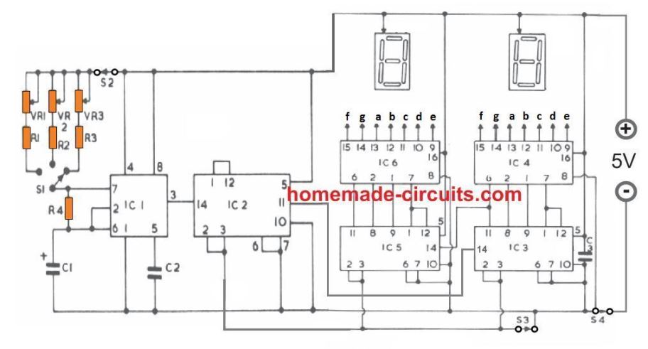
The addition of the IC2 enables the design to produce reasonably longer time delays through an ordinary IC like the IC 555, since it converts the single pulse time intervals from the IC 555 into 10 times longer time intervals.
Thus, 1 second time periods from the IC 555 gets converted into 10 seconds, 10 seconds gets converted to 100 seconds, and 1 minute is scaled up to 10 minutes.
IC2 also allows the timing capacitor C1 to be relatively smaller and compact.
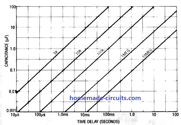
However, if you want the output delays many times higher than this, then IC 555 could be replaced with a more accurate timer IC like the IC 4060, for enabling bigger selectable ranges which can be 10 times higher than the proposed ranges.
The circuit has a 3 way selector switch, which can be used for setting one of 3 timing ranges. Each timing range has its own separate variable resistor or potentiometer which can be calibrated to further to breakdown each range into smaller time interval divisions.
Counter and Display Module
The counter and the display stage is built using IC3, IC4, IC5, IC6 and is used for showing the lapsed time intervals over a 2 digit 7 segment LED display.
The divide by 10 pulses from IC2 is applied to pin#14 of IC3, which is a binary decimal divider IC. IC3 converts the divide-by-10 pulses from IC2 into binary coded output across its pinout numbers 11, 8, 9, 1, and 12.
These binary signals are fed to the pins 6, 2, 1, 7 of IC4 which is a decoder-divider IC. The function of IC4 is to convert these binary signals into an appropriate sequence which can be interpreted as digital numbers over the attached 7 segment common anode display.
The pair IC3, and IC4 are able to process pulses upto 9 counts, after which it is carry forwards the signal to the next counter display stage consisting of IC5 and IC6.
IC5 and IC6 works exactly the same way as IC3, and IC4, but its job is to process the pulse counts higher than 9 pulses, so that the timing count above 9 can be correctly displayed over the two displays, upto the figure 99.
The integrated circuits from IC2 to IC6 all being TTL ICs require a regulated 5 V supply and therefore the circuit must be strictly operated through a 7805 IC.
How to Operate
Operating the proposed simple digital timer circuit is very simple:
Switch S4 is the ON/OFF switch which is shown on the negative line with no specific reason, it can be put on the positive line as well.
When power is switched ON through S4, the two displays may exhibit random irrelevant digits, which can be set to zero by opening the switch S3 momentarily and closing it.
Now, if the switch S2 is in the the switched ON position the digital timer will now start counting and displaying the ongoing counting process through the 2 common anode LED displays, and as per the selected time range.
If the switch S2 is in the OFF position, the timer will stay in the standby mode, and start the counting as soon as S2 is switched ON.
Digital Timer Parts List
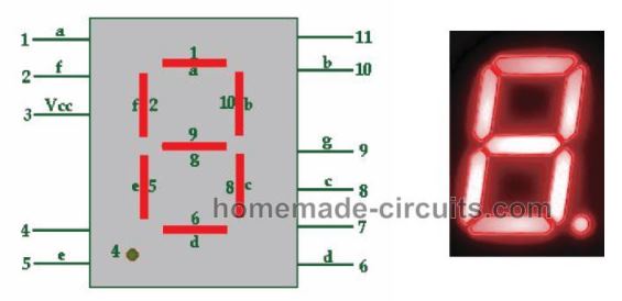
7 segment common anode display pinouts


Comments
Hello sir,
can you explain what I need 14 270 ohm resistors for the numeral displays?
It will helpful, thank you.
Hi Dab,
You will need to connect the 270 ohm resistors in series with the display pins a, b, c, d, e, f, g:
https://www.homemade-circuits.com/wp-content/uploads/2020/06/common-anode-7-segment-display-pinouts.jpg
Do you by any chance use kicad? I’m trying to replicate the same circuit but have trouble knowing which should be connected to which.
Hello,
I am building a similar circuit however the output is going to several 7400 series logic gates which feed into 8 16 segment cathode display.
The 8 displays are clocked into 4 states which I believe I have ironed out. However my problem is the load this draws. I’ve tried several different transistor configurations where to no avail (although I haven’t tried any mosfets yet). Are there any projects that have done similar things? Thanks in advance.
What type of load are you referring to and how is this load connected to your circuit?
OK, I guess you are referring to the LED displays. The LED displays can be easily driven using BJTs like 2N22222 or 8050.
Would you mind if I sent you a DM of a link to my dropbox photo showing my circuit? Ive tried several times posting it here on different browsers and I think whats happening is that it is not be allowed to go through on this site.
Actually any comment with a https link is sent to the trash folder, but no issues I always check the trash folder and restore all comments that are important. I have answered to your previous comment with the image link.
Well…. so this is what I have. Apologies in advance as i dont have any CAD program so i just drew this out. Hopefully you can see it. If not can I email this to you.
https://www.homemade-circuits.com/wp-content/uploads/2022/11/display-current-consumption-problem.jpg
This is what I have a nutshell. I tried to make this simplistic as possible. I can say that without connecting the displays and the 7400 ICs that I do see a solid 5V and consistent clock pulse from the emitter.
Unfortunately once I do connect this.. the 555 timer just flat lines to about 1-2 volts and doesn’t pulse.
I have tried configuring for a higher voltage output from the transformer and using a 16V output voltage regulator but then I’m afraid that the “logic high” will be too much for the flip flop.
I’ve also tried multiple voltage regulators (both 16V and 5V) and I still don’t get the right signature I’m supposed to get. I also know that probably doing that is not the most efficient way either.
I suppose what I am asking is what am I doing wrong here .. any help is appreciated.
Thank you Marcos,
Did you try using a separate 7805 IC for the displays? Meaning, you can use two 7805 regulators ICs, one for the IC 555 and one for the displays….
Hi Swagatam,
So yeah I’ve tried several different various combinations of separating ICs and the displays with the regulators. I dont know if you saw but the part numbers I’m using are indicates in the drawing I have.
Thank you though. Your comment made me go back and try various things over the past week that can possibly be causing this error.
So, I was however able to investigate more. I noticed that no matter how I configured the circuit the symptom was the same. When I did not connect the “load” (ICs, displays) my 555 timer output was solid. I noticed that Pin 2 was able to go below 1/3 of the supply voltage. Whenever I did connect the “load” like I’ve mentioned previously the output flatlines and does not go completely to 0V. Pin 2 likewise is above a 1/3 of the supply voltage.
Something is feeding back into the timer (I think) but I have no idea what it is.
Hi Marcos,
According to you the 555 fails to oscillate only when the displays are connected, otherwise the 555 IC stage oscillates normally.
In that case you can check the response by completely isolating the power supply to the displays by using an external 5V DC source from a different transformer or SMPS.
Just make sure to connect the ground lines of the two power supplies in common.
I would like to measure the time it takes students to run between two light gates. Is there a circuit that would allow me to do this?
I think the following circuit could be used for your application:
https://www.homemade-circuits.com/arduino-stop-watch-circuit/
Hi Mr. Swagatam
Good day! I would like to make timer with buzzer can you help me, how can I connect my buzzer in this circuit. Many Thanks!
Hi Henry, A buzzer may not be possible in the above circuit since all the relevant points are in pulsed form.
Instead you can try the following concept for the buzzer attachment
https://www.homemade-circuits.com/how-to-make-simple-versatile-timer/
Thank you so much for your quick reply. I will try the circuit and let you know what happens. Stay well.
No problem!
Good morning,
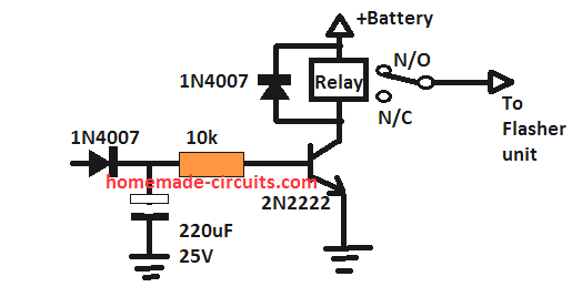
I would like to make a timing circuit, a delay on break, to hold the turn signal flasher on for about 3-5 seconds each time a momentary initiation is sent by the turn signal lever in my truck. I know GM uses this but Ford does not, (which I have). I could probably do this with a standard delay on break timer but I don’t know how do make the circuit with only 1 timer since it has to control both the left and right turn signals. Thank you for your time.
Regards,
Joe
Hi, I think you are looking for a delay OFF timer.
You can add the the following circuit in between the turn signal switch and the flasher unit.
Hello.
Thanks for your reply.
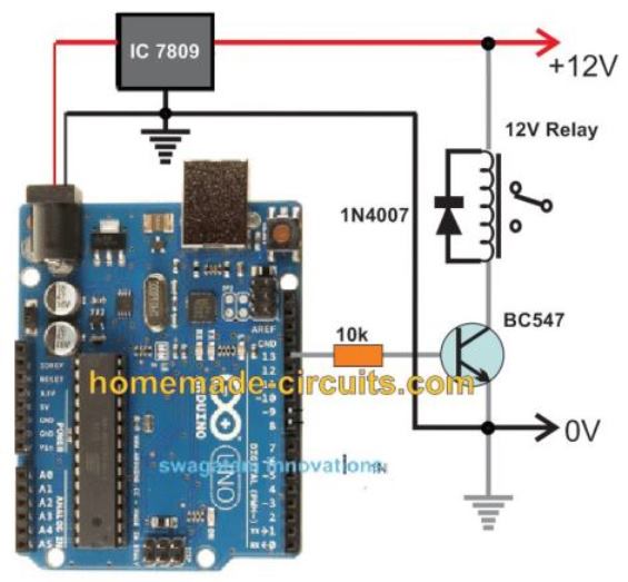
Can I use above circuit as transistor relay drive?
As pin 3 is output of 555 so can transistor relay drive be connected with pin 3 of 555?
The IC 555 pin3 output will give very short time delays, whereas pin11 of IC2 will give much longer time delay. You can use both these pinouts for connecting the transistor relay driver, as per your requirements.
Ok sir. Many thanks for your kind assistance.
You are welcome Adnan.
Hi Mr. Swagatam,
I am a good reader of your projects.
I am requesting that you help me with a design of electronic timer clock for switching on security lights at 1800hrs and off at 0600hrs daily.
Thank you paul, you can try implementing the first circuit from this article.
2 Best Long Duration Timer Circuits Explained
Hello.
Please let me know, how can I add a relay to control any AC/DC object by using this simple timer circuit.
Hello, you can add a transistor relay driver at pin#11 of IC2