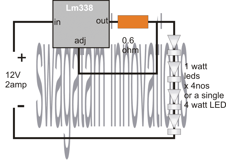
This 4 watt LED driver is a device that will illuminate a 4 watt LED safely through a constant current circuit using the IC LM338.
The IC LM338 as we know is a highly versatile device when it comes to controlling voltages and current levels.
Circuit Configuration
In the present design, the device is configured in the automatic current control mode.
White LEDs specifically need a well dimensioned input, technically the current to these LEDs must be strictly controlled.
By connecting its ADJ pin with the output makes sure that the current at the output is constantly monitored by the ADJ pin and is never allowed to go beyond the predetermined level set by the 0.6 Ohm resistor.
The device can support at least 3 amps of current through it, therefore easily becomes compatible for driving 1 to 5 numbers of 1 watt LEDs, each having their own current limiting resistors.
The current limiting resistors can be experimented with, probably lesser values may be tried for increasing the brightness levels of the LEDs, however anything less than 50 Ohms should not be tried, because it might cause a permanent damage to the LEDs.
Circuit Operation
The input to the LM 338 IC can be from an regulated DC power supply, capable of supplying 12 volts at 3 amps or more.
The IC LM 338 should be mounted over an heatsink for better performance.
The input diode should be rated at 3 amps, so a 1N5408 becomes OK for the application.
If the circuit is intended for operating outdoors, the input may be taken from a 12 v battery, like from an automobile battery.
Thus the proposed 4 watt LED driver circuit becomes especially suitable for illuminating vehicle interiors, for example as a roof light etc.
Calculating the Limiting Resistor
The formula for selecting the resistor value if a single 4 watt LED is conected is R = 1.25/LED current.
Here, LED current = 4/3.3 = 1.21A
Therefore R = 1.25/1.21 = about 1 ohm (0.6 is not correct)
R watts = 1.25 x 1.21 = 1.5 or 2 watt
for 4 nos 1 watt LEDs, total current is 300mA
Therefore R = 1.25/0.3 = 4 ohms
Circuit Diagram
You would also want to make a transformerless SMPS version of a 1 watt to 12 watt LED driver circuit
Parts List
- LM338 IC = 1
- 1 watt, 350 mA LEDs = 4
- 0.6 Ω 1 watt Resistor = 1



Questions & Answers
Use two strings of two leds each and connect them in parallel at the output of the above shown circuit.
The resistor can be calculated with the help of the given formula.
please provide the circuit for 3w automatic emergency light and how many LED's need to put in this circuit
you can try this circuit:
https://www.homemade-circuits.com/2013/02/make-this-automatic-10-watt-to-1000.html
hey what is about current….is it constant with voltage…..???
current is constant, not the voltage, voltage needs to be constant from the source.
please sir,what is amount of current that ic338 can give out as output if I use a 12v 300ma input by setting the ic to 5v?can I get the same 300ma current at the output?
you will get full 300mA, it won't be affected.
Swagatam sir Your blog is useful and very pleasant
Can you help me please provide transformer less 5w led AC circuit
thanks satheesh, you can try the following design:
https://www.homemade-circuits.com/2014/02/simple-1-watt-to-12-watt-smps-led.html
Swagatam sir Thank you so much!, I will try it.
hello sir, I need your help in designing a LED driver from car battery.
the input voltage will be ranging between 8 to 16V and the required output voltage is constant 24V and 950 mA current( if possible then need to have a very low value capcitor)
Thank you sir
hello, you can probably try the following concept:
https://www.homemade-circuits.com/2014/11/12v-car-laptop-charger-circuit-using.html
hello sir, I need your help in designing a LED driver circuit for running two 10W LED connected in series with a forward voltage of 10-11 V and current 850-950 mA. The input for the circuit will be a car battery which has ranging voltage from 8 to 16V.
The output expected is constant 24V and 850-950 mA, please help me sir.
Thank you very much.
hello syed, you can simply connect the above explained LM338 current controller in between the source voltage and the LED, and achieve the required results…however at 8V the LeDs will become little Dim…
but make sure to the LEDs in parallel….
and set the LM338 resistor to limit current at max 1.8 amps
Hi, I like to connect 4 nos 1 watt led (3.3v, 300mA) with 12v lead acid battery. So it required a resistor of 4 ohms (R=1.25/0.3= 4 ohms, R watts= 1.25*0.3= 0.37 watts).So what should be the wattage for resistor for better safety? 1/4 watt or 1/2 watt?
Hi, it should be 1/2 watt for better safety.
I will be using a 12v battery. how to get a constant 12v from that battery to connect the 4x1w led? Because 13.5v will be fully charged battery?
If you put 4 LEDs in series then 13.5V will be perfectly alright, however for current control you may have to add the following concept between the 13.5V source and the LED string
https://www.homemade-circuits.com/2013/06/universal-high-watt-led-current-limiter.html
Sir Good day!! do you have a led circuit for IC m74hc595bl? tnx Sir
Hi Jindro, I do not have the circuit using M74HC595, but its function looks quite similar to the IC 74LS164, you can check out the following article and see if it satisfies your requirement?
https://www.homemade-circuits.com/2014/08/knight-rider-led-scanner-circuit.html
Indeed you are a genius, naturally blessed with gift of electronics. May God be with you forever. Thanks for sharing your knowledge and understanding, We appreciate. Sir, I want you to design me a circuit or a voltage booster schematic that can amplify 1v to 15v and can deliver minimum of 30a and above. Once again, remain blessed. Hoping to hear from soon. Thanks, we love and appreciate your work…..
Thank you Hamzah! I am glad you liked my site! In order to get 15V 30 amps from a 1V source, the 1V source must have the capacity of at least 450 Amps and higher. Do you have this high level of amps for the 1V source? If yes, then it may be possible to create one