In this post I have explained a simple IR remote control circuit which can be used for controlling many appliances independently through a single transmitter handset. The idea employs ordinary components like IC LM567, IC 555 and does not incorporate microcontroller devices. The idea was requested by Mr. Saeed Abu and also other dedicated readers of this blog.
Technical Specifications
bro thanks for your reply. Please develop a simple Infrared (IR) Remote Transmitter/Receiver Circuit diagram.
My requirement is:
1) It must be specified for its transmitter. No interference with TV/Vcd remote or any other type of remote.
2) It(receiver) should be powered by Ac 220v.
3) It(receiver) can be used for multiple load (Light+Fan+..+..) by one transmitter
4) Please develop it very simple.

The Design
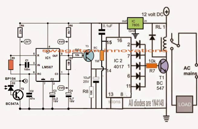
The following design depicts the basic IR receiver module using the IC LM567. The involved stages can be grasped with the help of the following points:
The IC LM567 which is a tone decoder IC or more simply a frequency decoder IC is rigged to produce a particular frequency determined by R3 and C2.
This frequency becomes the bandpass frequency of the circuit such that the circuit now gets locked on this frequency.
The input pin#3 of the IC is attached to a photodiode device for receiving an IR signal which may be tuned to the above set frequency of the IC.
This means that the circuit will now respond whenever D2 detects an IR frequency tuned to the frequency determined by R3/C2 of the configuration.
On detecting a coded frequency from a relevant transmitter the IC M567 output pin8 becomes low and stays in that position until the transmitting signal is prohibited.
Thus this circuit becomes the receiver module and may be triggered by a transmitter circuit tuned at the relevant fixed frequency.
The IC2 which is a Johnsons decoder divider IC is wired as a flip flop circuit, it's integrated to pin8 of the IC LM567.
As long as no signal is detected by D2, pin8 of IC1 remains high, the moment a signal is detected, T3 is triggered, which in turn triggers pin14 of IC2.
The above situation prompts IC2 output to change state thereby either activating RL1 and the connected appliance or deactivating them depending upon its initial condition.
For controlling multiple gadgets using a single transmitter handset, many of the above modules may be constructed and integrated with the corresponding appliances for the intended switching.
Circuit Diagram
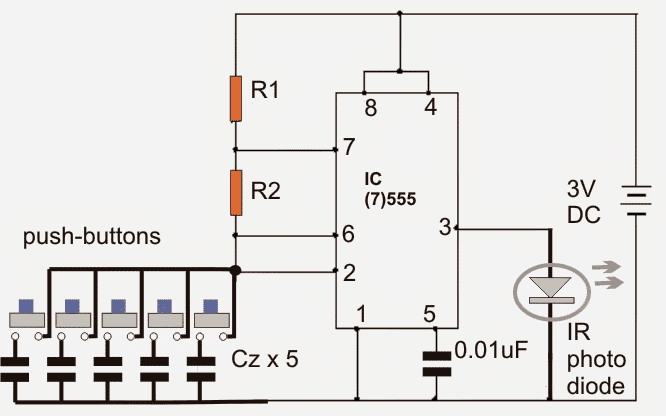
Controlling multiple appliances using the following single IR transmitter circuit
The following circuit forms the transmitter module of the proposed IR remote control for activating multiple gadgets.
It's a simple IC 555 astable circuit, whose output frequency is determined by the 5 individual capacitors and should be appropriately matched with the particular receiver circuit modules as discussed in the above section.
The capacitors attached with the respective buttons should be calculated and matched such that on pressing the relevant button, the corresponding receiver gets triggered for toggling the corresponding appliance.
R1, R2 may be chosen arbitrarily, but Cz must be selected in accordance with the receiver module frequency determined by R3 of the module.
Multiple Frequency Transmitter Circuit



Questions & Answers
Hi Swagatam
For an astable 555 vibrator, the timer will oscillate only when the timing capacitor is connected. The momentary connection due to the pressing of the push button will allow the oscillation momentarily…….in practical there will be oscillation for only a fraction of a second or no oscillation. And I wonder, if that momentary oscillation will trigger the receiver module.
Hi Abu-Hafss,
yes momentary connection is what we want from the transmitter…if it's pointed correctly toward the receiver, the response will be instant, moreover the user has the option of keeping the button pressed for a few seconds until the receiver responds
dear swagatam,
seen that the 4017 is connect as an flip flop, it can be replaced with another IC for example the IC 4047 or ne555?
for to activate more appliances i must to built more received circuit of first diagram?
on the first diagram the value of R3 depend from the frequency for set, but in that order of values?
d1-d6 can i use 1n4148 or what other type?
thank you so much
best regards
andrea
dear Andrea,
no, 4047 or 555 cannot be used for 4017
yes more receivers for more appliances
R3 will need to be made different for different receivers
d1-d6 = 1N4148
dear swagatam,
thank you for your help.
can you tell me if i can to use another IC instead the 4017.
in this moment i haven't this component.
thank you so much
regards andrea
dear andrea,
you can replace the 4017 circuit entirely with 4093 flip flop, you can refer to it in the following article
https://www.homemade-circuits.com/2011/12/build-these-simple-flip-flop-circuits.html
good,
i have a couple of 4093 in my box,
so i can just make this circuit.
thank you..
I follow you with great passion…
regards
andrea
that's great Andrea! thanks
thanks Swagatam, I think its what i was looking for.
It's my pleasure, Rahul!
whats the best way to find the frequency for each component to be controlled? for example and LCD TV, a cable tv box, a bluray player, and a radio? can you provide values for R1 and R2 and Cz?
can you provide values for R1 R2 and Cz? or let us know how you would calculat these values?
thanks
frequency for each LM567 module may be fixed by using the following formula
F = 1/R3xC2
Accordingly to get a matching set, the relevant capacitor from the 555 may be determined by using a online 555 frequency calculator.
R1 and R2 may be selected as 220K
the idea is to select a slightly different frequency for each Tx/Rx set with each set having an exactly matching frequency, this matching or pairing can be also done by using a frequency meter.
Frequency measuring option is normally available on all digital multimeters.
I want make operate 2 relays with two push buttons for curtain motor. request indicate the relevant capacitor and resistor values for my 2 receiver circuits plz
you will have to do it by calculating and also by practical testing through trial and error. I cannot provide the values because the calculated results and practical results could vary and may not precisely match.
Cz capacitors are polarized or non polarized?
since the capacitors will be very small in value, they will be non-polar for sure.
F = 1/R3xC2 in this C2 is in uf and R in Ohms isnt it
C2 in Farads, R in Ohms.
can i change the C2 of main circuit as required? (47nf)
yes you can do, you will need to fix the Tx frequency also accordingly.
sir, what is the purpose of the 5 buttons?
for toggling 5 appliances separately….
Dear Swagatam,
As you said in the circuit request:
– It(receiver) should be powered by Ac 220v.
But it is clear form the circuit that the IC need an external 12V DC source ?
How I can do it without external power source or with 220V AC
Dear Ahmed,
Any standard 12V/1amp AC to DC adapter can be employed for powering the circuit
Can is use your transformerless power supply circuit that you published in the following link in order to supply this circuit:
https://www.homemade-circuits.com/2012/08/high-current-transformerless-power.html
No, use only a good quality 12V AC/DC 1 amp adapter for supplying the circuit.
thanks dear for uploading my requested circuit.however i request u for ac operated receiver circuit u did not.pls do it also did u check the circuit?
you can use a 12v AC/DC adapter to power the Rx unit…
no I haven't tested it practically.
Can ordinary photodiode be used in place of bp104
yes any photodiode can be used
Sir swagatam,sorry sir,what type and part number of transistor T3? I can't see from your receiver circuit..
Hi Khairi, it's a BC557 or any similar small signal PNP will do….
Thank you so much sir..
Bro is it tested circuit diagram?
Bro, it's not yet tested, but if were to make it I would succeed with the results 100% sure, the design is very obvious and there's no way it can fail….but it's not for the newbies, if a newcomer tries it there could be a 100% chance of failing…
Sir,
If the transmitter circuit frequency are 218.59 Hz and recever circuit frequency are 217.76 Hz then it will work or not ?
Actually I'm trying to say that the both frequencies are same as point to point ?
Narottam, I am not sure how accurately the IC is specified to detect the frequency…you can check its datasheet to find the level of accuracy this IC may be featured with, however a difference of 1 Hz might be too less and the IC would not be able to differentiate this minute difference
ok..
thanks sir..
Hi Swagatam,
The LM567 datasheet says the max power supply voltage is 9v. Are you sure we can use 12v? The datasheet also says it can run at 5v. Can I? Because, I would like to run it at 5v.
Thanks,
Vijay
Hi Vijay,
yes, you can use 5V for the LM567 section, I'll update the diagram accordingly soon.
Hi Swagatam,
Thanks. Can you let me know the range of frequency that I have to target. Currently, I have no idea about the frequency at which the emitter and receiver can operate.
Thanks,
Vijay
Hi Vijay,
You can try anything between 1kHz and 500kHz
Hi Vijay,
did you tune the 555 frequency with the LM567??
the 4017 configuration presented by me is correct and foolproof…I have used all the outputs of the 4017 so that accidentally the output trigger may not get lost across the 10 outputs…this feature is not taken care of in your linked circuit.
I'll be deleting this comment because of the external link you have included in it.
…in my circuit just connect the pin15 to ground through a 1M resistor and connect a 0.1uF cap across pin15 and positive…this will never allow the IC 4017 to trigger the relay on switch ON
Hi Swagatam,
Thanks. I'll try that with the 4017. And yes I did tune the LM567 and it correctly works because if I press the button (within 10-12 cms), the relay energises and deenergises. I would like to know how I can increase the range.
Thanks,
Vijay
Hi Vijay,
"tuning" means that the IC 567 will respond only to the tuned frequency and not to any other frequency, did you confirm this?? because if it's tuned correctly then it will respond over greater distances comfortably.
you can try the same with your TV remote and see how it works.
Hi Swagatam,
Yes, I did conform that the IC 567 responds only to the tuned frequency and not to any other frequency. But the range is the problem. As I couldn't source BP104, I used an IR receiver LED (that looks like a normal LED but darker in colour. The IC doesn't pickup the TV remote signal as I haven't yet tuned to that. But I tried a different circuit with TSOP and it does pickup the TV remote input but I wanted something that doesn't pickup signals from remote controls as TSOP is too sensitive.
Thanks,
Vijay
Hi Vijay,
for experimentation, try 12V with the IC 555 circuit but make sure to use a 1K resistor in series with the photodiode, it could be the low voltage which is not allowing the LM567 to detect the signals from a greater distance.
if still the range does not improve, then you can try replacing the LM567 photodiode with TSOP…it will not pick the TV signals once it's tuned with a different frequency and matching with the 555 circuit…try these and see the response
Hi Swagatam, thanks and I'll do that. I always thought that the TSOPs respond only to a certain frequency (for ex 38KHz) and not anything other than that. If a TSOP can pickup the frequencies I'm trying, that would be great.
Regards,
Vijay
Hi Vijay,
yes that's correct, TSOP are designed to pick only between 30 to 40kHz, but we can modulate this frequency with another frequency for making it unique, first check it with LM567 at its specified carrier frequency if it works for greater distance then we can modify it differently.
Hi Swagatam,
I built the circuit but for remote control, I used an RF pair and it works like charm.
regards,
Vijay
Hi Vijay,
OK that's great…keep up the good work.
Hi Swagatam,
I'm looking for a circuit that could control a 12V DC fan, during a specific period of time after power-off (therefore a battery and charging circuit would have to be present as well). In other words, when power is applied, the fan would run and at the same time the battery would be charged. As soon as power went off, the fan would cotinue to run during a time set, in minutes. I don't supose you have something similar, do you?
Best regards, and keep up the good projects…
Nélio
Hi Nelio,
It can be implememnted by using the following circuit modules:
https://www.homemade-circuits.com/2014/11/long-duration-timer-circuit-using.html
in the above circuit, the push button can be removed and the cap/resistor junction can be connected to a 12V DC from a mains adapter while the shown 12V supply to this circuit could be achieved from a battery
the 2m2 and the 1000uF cap will need to be correctly selected for desired time delay.
for an auto charging the battery, the second circuit from the following link could e tried:
https://www.homemade-circuits.com/2011/12/how-to-make-simple-low-battery-voltage.html
Hi Swagatam,
Thanks. By the way, you probly get the same request in another post. Ignore it please. When I was posting this request in this circuit, my browser crashed, and I wasn't aware if it was published or not.
Best Regards.
Nélio
Hi Nelio,
No worries, I have deleted the repeat comment…thanks!
Hi Swagatam,
In this circuit, the transmitter has 5 capacitors, each one with its push button. You have named them Cz…. are all 5 the same value? Or are they all of diferent values?
Best Regars.
Nélio
Hi Nelio,
All the capacitors needs to be of different values, so that different corresponding frequencies are generated through the selection, assigned for controlling the relevant appliances individually without interference.
Hi i have a birth day tone circuit.Now i want to convert it as a Door calling bell which will be operated with 3v battery.how can i do that pls help me.
Hi Saeed,
you can try the following circuit set up
https://www.homemade-circuits.com/2015/05/simple-musical-door-bell-circuit.html
Sir, I want to make a circuit with multiple mode operation.
For example, I want to design a remote with two buttons and two different outputs.
For that I am using to use same transmitter circuit as yours. With two different Czs. Of frequencies 38 KHz and say, 40 KHz.
If I use two different TSOP circuits at the receiver, that is TSOP1738 and TSOP1740, will that work?
I am planning to connect 1 uF Capacitor at the output of both the TSOPs.
Thanks in advance.
Chaitanya, I think that would work only because of the presence of the LM567 IC…which will effectively distinguish the two frequencies and allow only the selected one for the particular set….so I think that will do…
Sir,
I tried to make this but I did not success.
So, I want to make a simple remote control home appliances only control a single appliance and as remote I want to use CR2025(this is a remote control of small audio amplifier machine, 21 bottoms).
So, please help me….
Narottam, if it's an IR remote then probably you can make a receiver circuit by using the following concept:
/blog/2016/02/tv-remote-control-tester-circuit.html
a flip flop can be attached with the last transistor for controlling any gadget
And sir I want to use a mobile charger for power supply…
Sir,
Is it possible.. to make remote control home appliances(more appliances control by one remote) by using Encoder-Decoder…
If possible then help me by giving the circuit diagram & instructions.
Thank you..
Narottam, yes it's possible, but it's better to buy the module than of making at home, since the readymade version is perfectly optimized and assembled on a good quality PCB.
You can buy a 4 relay or a 8 relay module and wire them with the respective appliances…..all these could be operated from a single remote handset having 4 or 8 buttons.
Hi Swagatam
I have been experimenting with the LM567 as I want to build a IR gate lock, I have tried the circuits on here and elsewhere with limited success, but I am making progress in the right direction. I built this one tonight and yeah I have a winner,sort of. The problem I have is with the transmitter, I am powering it from the same voltage source as the receiver circuit and when I power it with its own separate power source it fails to register with the receiver. Just wondering if you shed some light on this problem.
Regards
Geoff
Hi Geof, if the circuit is responding only when a same power supply is shared by the transmitter, then I am afraid that's not correct because that implies the LM567 frequency could be leaking through the power supply into the 555 IR diode and transmitted back to the LM567 receiver.
The transmitter should be able to make the Rx work using separate power supply or a battery.
I think the IC 555 frequency might not be matching correctly with the LM567 frequency….did you verify whether the frequencies of the two modules were exactly similar or not….please confirm this first in order to assess the operations correctly.
Alternatively, if you have a spare LM567, you can use it as the transmitter by using identical RC components as used in the receiver unit, this would enable a perfect matching of the frequencies and thereby utilization of separate power supplies.
Hello Sir,
Do you have a diagram for 3 output channel using only 1 receiver?
you can try this one
https://www.homemade-circuits.com/2013/07/simple-100-meter-rf-module-remote.html
Hello! Can you make a fix values for r3 , r1 , r2 and CZ?
Regards.
Hi Swagatam
Can you tell me what value R3 has to be at a frequency 10 Khz .
For the receiver.
Hi Jaap, the formula is:
F = 1.1/RC, C will be in farads
for more info you can refer to this datasheet
http://www.ti.com/lit/ds/snosbq4e/snosbq4e.pdf
Hi Swagatam
Can you please tell me how much R3 would be in K ohm.
For 10 Khz.
And could I replace R3 with a fixed resistance with a adjustable resistance in series.
Jaap, I have already answered to this question…please refer to my previous reply.
hi it’s oz your favorite locksmith lol
is there a way to build an IR blaster that can connect somehow to the alexa platform
and allow alexa to be “programmed” to control multiple devices like cable box, tv, dvd players, xbox?
Hi Oz, sorry I have no idea about it…
Mr. Swagatam I have remote control ckts with 4017 and stop 1738. But it automatically switches on and off due to spikes in electrical line.
The ckt given by you here is spike proof. Just I want to ask. Please reply.
RK Seth.
Mr. Rk, yes it is spike proof.
Ok I will try it. Then give you feed back.