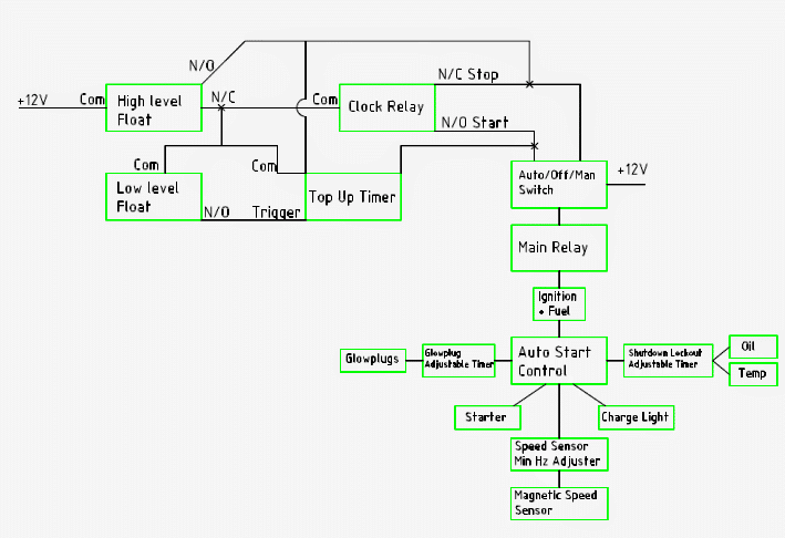
In this post I have explained a programmable Auto-Starter circuit which may be used for getting a pre-programmed set of automatic sequential operations over a Diesel Water Pump as intended by the user. The idea was requested by Mr. Scott.
Technical Specifications
I am currently trying to figure out how to make up an auto starter for a mates diesel water pump,
Motor has got:
- Glowplugs
- Fuel cut off solenoid,
- oil pressure switch
- water temp switch
- Charge light(from alternator)
Triggers:
- Programmable clock timer with outputs
- High level Water tank float switch
- Low level water tank float switch
Objective:
When start signal received via low level float switch contact or programmable clock output:
- Main relay energized
- IGN + Fuel is energized.
- OIL + water switch isolated
- Glowplugs are energized for adjustable time(variable resister or pot), then
- Motor will crank for an adjustable time(variable restistor?),
If engine starts as sensed via a magnetic speed sensor ( or maybe charge light switch? eg alternator light goes off received as engine start successful) for around 10-20 seconds without stalling.
oil pressure + water temp sender cutout switchs become active again and engine continues to run until main relay is tripped by either low oil/ water temp/ high level float switch or clock disconnect main relay
How ever If motor fails to start or stops within the 10-20 seconds or so, reset occurs, wait approx 10 seconds then goes for restart.
After approx 3 attempts trips out main relay and activates overcrank led light.
I hope this all makes sense, kinda hard to explain. If this is too confusing the main part I don't know how to work around is the engine start/restart for 3 cycles then overcrank cutout.
I think i could do the rest but it would be in an infinite crank cycle loop if failure to start occurred. Manual/Off/Auto would also be handy as well but i can work that pretty easy.
I have linked a site with much the same as what i'm trying to acheive but it has all the bells and whistles and the price to match. Plus can't learn anything going that way about it.
To Summarize:
Setup is kind of similar to the the Automatic Transfer Switch you have listed on your website.
Steps are:
1.start signal received
2.main relay energised
3.Ignition + Fuel energised
4.glowplugs timer(adjustable 1-60sec) starts
5.glowplug timer stops
6.oil + temp isolated timer start(1-300seconds)
7.engine start energised(adjustable .1seconds to around 10seconds)
8.engine cranks until crank time expires or magnetic speed sensor min Hz reached or exceeded(adjustable 13-2500Hz)
9.A a.wait 10 seconds if not running(alternator light on and or below speed sensor Hz)
b.crank rest timer start(adjustable 1-30seconds)
c.crank rest timer stop
d.go back , Repeat Steps 4.- 9. Max 3/5 times
e.if after 3/5 times no start, isolate main relay and activate overcrank light.9.B a.wait 10 seconds if still running(alternator light off and or above speed sensor Hz)
b.goto step 10.
10. oil + temp trips become active after timer finished
11. engine continues to run until:
a.stop signal received= main relay de-energised, engine shutdown
b. oil pressure/ water temp/ overcrank trips= engine shutdown, main relay isolated and tripped warning
light activated until manual reset
Also have pdf attached with most parts listed,
 The
The
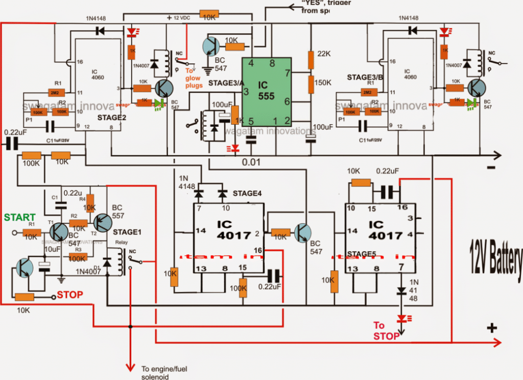
The Design
The proposed programmable Automatic starter circuit for diesel Water Pump can be understood by studying the following description and by referring to the diagram shown below:
Stage1: It's a simple transistorized latch circuit which responds to a positive signal (start) and latches ON its relay.
The relay may be wired up for triggering the fuel/ignition solenoid. This stage also powers up the rest of the circuit and switches ON stage2 such that the timer IC 4060 begins counting the time period set by adjusting its preset at its pin 10.
Stage2: While the IC 4060 counts, the relay at its pin3 powers the glow-plugs. As soon as the set time of IC 4060 in stage2 elapses its output pin3 goes high, activating the connected relay which instantly disconnects the glow-plugs from the supply shutting them off.
Stage3/A: With pin3 of the IC 4060 high at this point, pin4 of IC 555 in stage3/A resets and becomes active.
The connected relay at its pin3 clicks and starts the cranking the diesel engine. Since the IC555 is configured as a 10 second astable timer, it allows the cranking to go on for 10 seconds and then stops.
The high at pin3 of IC555 also makes sure that the high sequence from pin3 of the center 4017 (stage4) shifts to its pin2 activating the corresponding BC547 transistor, otherwise the pin3 relay of IC555 couldn't be activated.
Stage3/B: It's another timer stage which may be appropriately and separately wired up and used for activating the oil+temperature isolated stage simultaneously with stage3/A.
Stage4: After a delay of another 10 seconds, the output of IC555 yet again becomes high, however this prompts the stage4 IC 4017 to push its sequence further to 7. This enables two things to happen:
It stops stage3/A relay from getting activated and also sends a high from pin7 from stage4 IC to pin12 of IC 4060, such that the whole process is forced to repeat.....thus, stage2 again activates> glow plugs light up....until the engine starts cranking for 10 seconds via stage3/A IC555.
Stage5: The above movements are closely monitored by IC 4017 in stage5, its pin14 gets the signal each time stage4 IC prompts a reset of the whole cycle due to engine not responding to the cranks, and when this goes on for 3 times, stage5 IC pin7 goes high forcing a "STOP" signal to the transistor latch such that the whole mechanisms comes to a dead halt.
However, suppose the engine responds correctly and starts up before the three attempts are crossed, the RPM detector sends a "YES" signal to the NPN transistor connected with pin4 of IC 555 which instantly blocks the reset pin of the IC into a non-conducting state, so that the pin3 relay shuts off, deactivating the cranking of the engine and inhibiting any further "clocks" to the stage4/5 ICs


Comments
Do you have a PCB layout for the programable diesel pump start?
BOM List?
Thanks
Sorry, I do not have a PCB layout for this design….
Hello is there anyway I could purchase this circuit for me to wire into my application
Hi Swagatam
BEHTREEN CONFIGURATION HAE!!!
I would like to suggest that the NPN connected to the pin4 of 555 should simply be omitted, instead the pin4 should directly be connected to the alternator pilot lamp (coming from the voltage regulator). As mentioned by Mr. Scott, the alternator pilot lamp is ON as long as the engine is being cranked. As soon as the engine starts running smoothly that lamp goes off.
This is a simple approach otherwise, one also has to additionally install an RPM detection circuit+sensor.
Hi Abu-Hafss,
Thanks! If the lamp is a part of a 12V regulated output then the integration could be allright.
Hi Swagatam
The automotive voltage regulator (AVR) is normally a solid state device which I have already discussed with you last year. There are rare chances of having a mechanical relay type AVR. The relay or the transistorized circuitry is configured in such a way that the wire coming out of the AVR (designated for LAMP) has 12V as long as the engine is being cranked, and 0V when the engine is started. This particular wire is only connected to a pilot lamp in the instrument panel hence, it is well isolated from the rest of the wiring set-up.
Thank you Abu-Hafss,
you suggestion is good if the RPM detector is not included in the design, however the transistor stage that you are referring to has a few advantages: it helps to keep the configuration strictly electronic, moreover it also keeps the internal circuitry isolated from the outer non solid-state stages, a slightly different approach could be figured out to keep this transistor stage included…