In this post we diagnose a PIR activated message player circuit, which was sent by Mr. Norman Kelley one of the dedicated followers of this blog for improvements. I have explained more about the design through the following discussions.
Triggering Message Playback with a PIR Input
I have been working on a project for about a week and I can't seem to get it right. The objective of the project is each time a PIR is triggered by a person, a 20 second recording plays.The recorded message changes a total of four times. 1st trigger message one plays, trigger 2 and the second message plays, trigger 3 and the third message plays, trigger 4 and the last message plays, trigger 5 and the 1st message plays.I also want two red LEDs to light while the 20 second message plays.1)PIR output to step cd4017 thru four steps.2)CD 4017 output to activate pin 2 of an ISD1820 record/play chip.3)CD4017 to reset after four outputs.I have been able to step the CD4017 using a one shot NE555 circuit. I also used NE555 one shots to feed the CD4017 outputs to the pin #2's of each of the ISD1820. It seemed to work ok, but I've had a tough time getting the LEDs to light.I tried a combination NPN/PNP transistor set up but I never got everything to work right. I don't have enough electronics smarts to size the transistors and I keep getting interference between playing the recordings and the LEDs.I'm lost and I really need your help. Would you please design a circuit and post it for me? It would be nice if you would send me a copy of the circuit to my email or gmail. email is nkelley6@austin.rr.com and gmail is normankelley36@gmail.comI have attached the schematic for the subject PCB. I have a working model, but it runs the batteries down from 1.5v to less than 1v overnight even when there is no activity.So, something is draining the batteries. I am running it off of 6V because the PIR doesn't work correctly below 4.5 volts and I want it to operate correctly for a longer period of time. I am powering it with 4-aaa alkaline batteries.
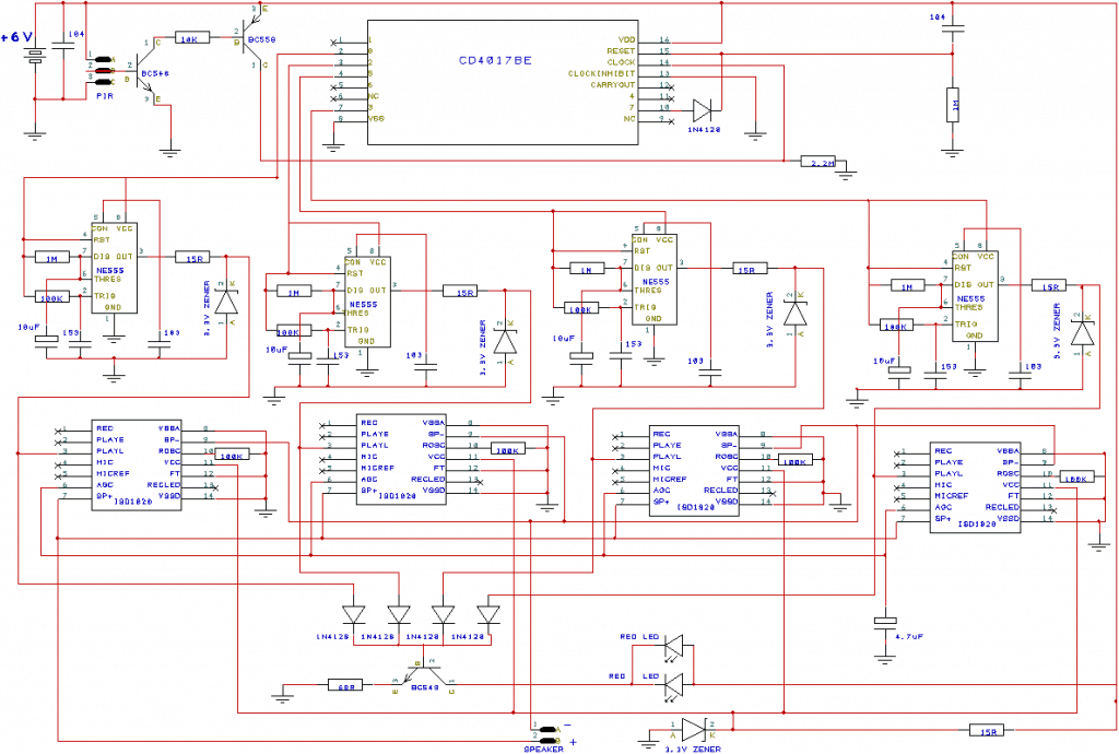
Circuit Diagram
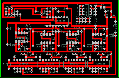
This is my PCB.I have jumper wires connecting A to A , B to B…..,3 to 3, 2 to 2…. and so forth. It seems to work pretty well, but I wonder if there is a better design.
Thanks for your help!
Norman Kelley
PCB Design
Analyzing Circuit Implementation
A casual observation makes us feel that the circuit is without any flaws, and practically too it seems to be working fine, however the design has much room for improvements and for making it technically more sound.
The design could be improved as discussed in the following points:
1) The IC 555 monostable stages are actually inappropriately configured with the IC 4017 stages, here the monostables are powered from the pinouts of the IC 4017 which doesn't technically too correct. An IC 555 based monostables must be powered directly from the supply rails, and triggered via its pin#2.
Therefore this issue prevalent in the above schematic can be corrected as indicated in the following diagram:
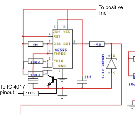
Now this looks much better, here the supply to the monostable is acquired from the circuits +/- DC power rails, while the triggering is acquired from the relevant IC 4017 pinout at pin#2 of the monostable.
Reducing Power Consumption.
As expressed in the request, the design also struggles with power consumption issues due to the involvement of many ICs, and each of them drawing over 7mA. The total consumption thus is able to get significantly high for any small battery.
To correct this, we need to make sure that during the stand-by mode except the IC 4017, remaining all ICs remain disconnected from the DC supply and are connected only as soon as the PIR detects a human presence and the message player is in the activated mode for the 20 second time period.
The exact procedure for implementing this can be seen below:
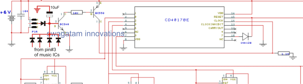
Here only the 4017 IC is powered from the 6V battery terminals while the rest of the circuit stages are powered from the collector of PIR PNP transistor BC559.
The idea is simple, the moment a human presence is detected, the PIR gets activated and powers the monostable along the message player circuit stages, the message player circuit responds to this and starts playing the recorded clip.
This audio signal is sent back to the PIR NPN transistor base and latches it ON so that now the entire circuit is able to remain powered as long as the message is being played.
The moment the message player completes playing the audio clipping and switches OFF, the PIR stage also switches OFF and consequently shuts off the entire connected circuit stage, until the next human presence is detected, and the cycle repeats...


Need Help? Please Leave a Comment! We value your input—Kindly keep it relevant to the above topic!