• Skip to main content
  • Skip to primary sidebar

Homemade Circuit Projects

Need circuit help? Post them in the comments! I've answered over 50,000!

Blog | Categories | About | Hire Me | Contact | Calculators-online
You are here: Home / Sensors and Detectors / Home Electromagnetic Radiation Detector Circuit

Home Electromagnetic Radiation Detector Circuit

Last Updated on January 1, 2024 by Swagatam 5 Comments

The assembly proposed in these lines is an electromagnetic radiation detector (power and others) that allows the user to organize their living space with full knowledge.

Table of Contents
  • Circuit Description
  • Testing and tuning

Circuit Description

The sensor used for this design is a simple wire coil (L1) associated with the MOSFET transistor (T1) biased at the beginning of its conduction zone by the tandem R1, AJ1.
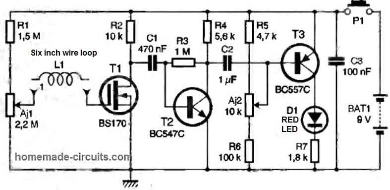
The frequency of the EMF induced in the coil L1 is recovered at the drain of T1 and strongly amplified. The signals thus amplified at the terminals of R2 are capacitively transmitted by capacitor C1 to a second common emitter amplifier stage, built around the NPN bipolar reference transistor T2.

The amplitude of the signal present on the collector of T2 depends not only on the intensity of the ambient radiation, but levels of over 100 mV have been recorded during tests near the oscilloscope used for measurement. Capacitor C2 provides the connection to the third and last transistor amplifier stage.

The base of T3 is biased by R5, R6 and the adjustable AJ2, which must be adjusted so that T3 is at the limit of blocking in the absence of radiation, thus causing the extinction of the LED D1 placed in the collector circuit.

In the presence of any radiation, the negative alternations of the signal recovered at the terminals of R4 cause the conduction of T3 and therefore the lighting of LED D1. Resistance R7 limits the direct current passing through the LED diode.

Since this assembly is only used occasionally and for the necessary duration to diagnose contaminated areas, a simple push-button switch (P1) serves as an ON/OFF switch. The decoupling of the power supply (a 9V 6F22 type battery) is ensured by C3.

Testing and tuning

To become operational, our detector requires two simple adjustments to be made.

First of all, it is necessary to place oneself in an area that is not (or little) disturbed by radiation, such as the center of a room, at a respectable distance from any electrical connection, including lighting, or preferably outside a dwelling and at a distance from any high voltage line.

After checking the correct orientation of the transistors and LED D1, AJ1 will be placed in the clockwise direction and the module will be powered under 9 V, taking care to temporarily short-circuit the P1 push button so as not to have to keep it pressed during the adjustments.

By turning the adjustable AJ2 alternately in both directions, one should go from the state of the LED being lit to the state of the "LED off." The correct adjustment for AJ2 is the one that corresponds to the state of the "LED almost off."

Using a high-brightness transparent package LED, one should barely see a reddish zone when looking at it from the front.

To adjust AJ1, it is now necessary to bring our module (a few centimeters) close to a source of radiation: a plastic wall socket, a television, a hi-fi system, the power cord of a bedside lamp, etc.

By turning AJ1 counterclockwise, it will be noted that for a particular setting, LED D1 lights up more intensely the closer one gets to the source of radiation.

By making small successive adjustments, one should arrange for the LED to start shining as far away as possible from the radiation source without remaining lit permanently when moving away from it, which would correspond to the permanent conduction of T1, and thus to a bad adjustment of AJ1.

This adjustment stage is more or less delicate, but within the reach of any amateur electronics enthusiast.

When the adjustable AJ1 is correctly adjusted, the detector is operational. You can then survey your immediate environment. We have personally observed that the detector reacted strongly to the approach of video or computer equipment even when we were still more than a meter away.

Clear detections were also observed at more than 40 cm from an alarm clock (now moved away from the head of the bed) and at 20 cm for the power cords of bedside lamps.

More surprisingly, for a chandelier under power, whose radiation was detected at more than 1.20 m even though it had no insulation defects after checking. We have observed the beneficial effect of the metallic shielding (connected to ground) of washing machines in service, whose radiation at a few centimeters was almost zero.

Since this home electromagnetic radiation detector circuit systematically reacts to the proximity of live wires, it can also be used to determine whether a socket or equipment, such as an electrical panel on which work is to be done, is indeed de-energized.

In this latter case, it may be interesting to replace push button P1 with a switch to ensure, throughout the intervention, that power is absent from the equipment in question without having to hold down the button.

There is no doubt that this small circuit will find a place in your measuring equipment and that you will find many opportunities to make it useful.

You'll also like:

  • frequency2Bto2BvolatgeIndustrial Valve Switching Detector Indicator Circuit
  • hall effect basicLinear Hall-Effect Sensor – Working and Application Circuit
  • frequency 13 Simple Frequency Counter Circuits Discussed
  • hall effect proximity sensor circuitProximity Detector using Hall Effect Sensor Circuit

Filed Under: Sensors and Detectors Tagged With: Detector, Electromagnetic, Home, Radiation

About Swagatam

I am an electronics engineer and doing practical hands-on work from more than 15 years now. Building real circuits, testing them and also making PCB layouts by myself. I really love doing all these things like inventing something new, designing electronics and also helping other people like hobby guys who want to make their own cool circuits at home.

And that is the main reason why I started this website homemade-circuits.com, to share different types of circuit ideas..

If you are having any kind of doubt or question related to circuits then just write down your question in the comment box below, I am like always checking, so I guarantee I will reply you for sure!


Previous Post: « Vehicle Body Metal Detector Circuit
Next Post: LM12 IC Datasheet, Application Circuits »

Reader Interactions

Questions & Answers

Total Posts: 5
Newest Oldest
Imran
July 14, 2024 • 2 years ago #154768

Sir, can treasure be found with this detector??

Reply
Jedidiah Isaaka
June 17, 2024 • 2 years ago #152952

Hello Sir. Thank you so much. Now, why is T3 used as a complementary transistor to T2? Is it not possible for both to be NPN transistors?

Reply
SwagatamAdmin
June 18, 2024 • 2 years ago #152960

Hi Jedidiah,
If NPN is used for T3 it wouldn’t amplify the T2 signals, rather just invert the T2 signals, whereas a PNP for T3 complements the T2 signals and amplifies it further to much higher levels.

Reply
Jedidiah Isaaka
June 20, 2024 • 2 years ago #153128

Thank you.
R3 (1M) is connected as a feedback. Is there any significant effect on the circuit’s operation when it’s directly connected to Vcc?

Reply
SwagatamAdmin
June 21, 2024 • 2 years ago #153137

The transistor T2 along with R3 are configured to work like a preamplifier, so the R3 must be connected at the exact position where it is shown, if it is linked with the Vcc the T2 preamplifier will stop working.

Reply

Need Help? Please Leave a Comment! We value your input—Kindly keep it relevant to the above topic! Cancel reply

Your email address will not be published. Required fields are marked *

Primary Sidebar


Categories

  • Arduino Projects (95)
  • Audio and Amplifier Projects (134)
  • Automation Projects (18)
  • Automobile Electronics (104)
  • Battery Charger Circuits (90)
  • Datasheets and Components (109)
  • Electronics Theory (150)
  • Energy from Magnets and Earth (41)
  • Games and Sports Projects (11)
  • Grid and 3-Phase (20)
  • Health related Projects (27)
  • Home Electrical Circuits (13)
  • Indicator Circuits (16)
  • Inverter Circuits (98)
  • Lamps and Lights (161)
  • Meters and Testers (72)
  • Mini Projects (28)
  • Motor Controller (68)
  • Oscillator Circuits (30)
  • Pets and Pests (15)
  • Power Supply Circuits (91)
  • Remote Control Circuits (50)
  • Security and Alarm (65)
  • Sensors and Detectors (107)
  • SMPS and Converters (46)
  • Solar Controller Circuits (62)
  • Temperature Controllers (44)
  • Timer and Delay Relay (50)
  • Voltage Control and Protection (44)
  • Water Controller (37)
  • Wireless Circuits (31)


Circuit Simulator

circuit simulator image


Subscribe to get New Circuits in your Email


Other Links

  • Privacy Policy
  • Cookie Policy
  • Disclaimer
  • Copyright
  • Videos
  • Sitemap

People also Search

555 Circuits | 741 Circuits | LM324 Circuits | LM338 Circuits | 4017 Circuits | Ultrasonic Projects | SMPS Projects | Christmas Projects | MOSFETs | Radio Circuits | Laser Circuits | PIR Projects |


Recent Comments

  • Swagatam on Simple Delay Timer Circuits Explained
  • Maddy on Simple Delay Timer Circuits Explained
  • Swagatam on HX710B Air Pressure Sensor Datasheet, How to Connect
  • Swagatam on Simplest One Transistor Regulated Power Supply Circuit
  • Luciano Orozco on HX710B Air Pressure Sensor Datasheet, How to Connect

Social Profiles

  • Twitter
  • YouTube
  • Instagram
  • Pinterest
  • My Facebook-Page
  • Stack Exchange
  • Linkedin

Calculators

  • ZVS Induction Heater + Tank Calculator Tool
  • Zener Diode Calculator
  • Wire Current and Thickness Calculator (Ampacity Calculator)
  • Voltage Divider Calculator
  • Transistor Base Resistor Calculator
  • Transistor Astable Multivibrator Calculator
  • TL431 Calculator
  • Solar Panel, Inverter, Battery Calculator
  • Ferrite Core Air Gap Calculator Tool
  • Parallel MOSFET Calculator Tool: How to Connect MOSFETs in Parallel Safely
  • LC Resonance Calculator for EV Battery Charger Circuits
  • LED String Series Resistor Calculator
  • Calculator to Design a High Power 3kW PFC (Power Factor Correction) Circuit
  • Passive Power Factor Correction (PFC) Calculator
  • LM567 IC Calculator Tool
  • SMPS Flyback Boost Converter Calculator
  • Shunt Resistor Calculator for Ammeters
  • SCR and Triac Gate Resistor Calculator
  • Battery Back up Time Calculator
  • Boost Converter Calculator (Non-Isolated)
  • Bootstrap Capacitor Calculator
  • Buck Converter Calculator
  • Buck-Boost Converter Calculator
  • Capacitance Reactance Calculator
  • DCM Flyback Transformer & Wire Gauge Wire Size Calculator Tool
  • Filter Capacitor Calculator
  • IC 4047 Calculator (Frequency and PWM)
  • IC 4060 Calculator
  • IC 555 Astable Calculator
  • IC 555 Monostable Calculator
  • IC SG3525, SG3524 Calculator
  • Inductance Calculator
  • Induction Heater Inductor and Resonant Frequency Calculator
  • Induction Heater Work Coil Calculator
  • Inverter LC Filter Calculator
  • LC Resonance Calculator
  • LED Current Calculator
  • LM317, LM338, LM396 Calculator
  • NAND/NOT Gate RC Values Calculator
  • NOT, NAND Gate Frequency Calculator
  • Notch Filter Calculator Tool
  • Ohm’s Law Calculator
  • Phase Angle Phase Shift Calculator
  • Power Factor (PF) Calculator
  • RC Filter Calculator
  • Reactance Calculator
  • Sine Table Calculator for SPWM Arduino Code
  • Small Signal Transistor(BJT) and Diode Quick Datasheet
  • SMPS Calculator for Toroidal Ferrite Transformers
  • SMPS Flyback Transformer Calculator – Design by Target Duty Cycle
  • TL431 Calculator

© 2026 · Swagatam Innovations