In this article I have explained a circuit design which will help to optimize the torque of an induction motor used in electric vehicles, by analyzing its current consumption.
Using a IC 555 Inverter for Toque Control
The design is specifically intended for electric vehicles which are designed to work with induction motors, and therefore here an inverter is included for operating the induction motor from a battery.
The proposed automatic torque optimizer circuit for induction motor can be witnessed in the following diagram. Since it’s designed for an electric vehicle, an inverter circuit is included, and built using an IC 555.
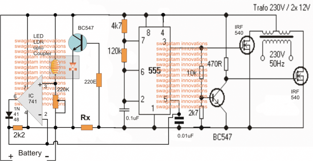
The IC 555 along with the associated mosfets and transformer forms a decent inverter circuit for driving the specified single phase induction motor from a 12V or a 24V battery. For a 24V battery the IC section will need to be stepped
down to 12V through a suitable voltage regulator stage.
Coming back to the actual design, here we need to make sure that the induction motor connected with the transformer initiates with a lower speed and begins gaining momentum, speed and torque as it gets loaded.
Using PWM Technique
Basically to implement this, a PWM becomes the best technique and in this design too we take the advantage of the IC 555’s built in PWM optimization feature. As we all know that the pin#5 of the IC 555 forms the control voltage
input of the IC, which responds to a varying voltage to adjust the pulse width level at its pin#3, meaning for higher potential levels at pin#5, the pulse width at pin#3 gets wider and for lower potentials at pin#5, the pulse width at pin#3 gets narrower.
In order to translate the load specification into a varying voltage at pin#5, we need a circuit stage capable of converting the rising load on the induction motor into a proportionately rising potential
difference at pin#5 of the IC 555
Role of Current Limit Sensor
This is done by introducing a current sensing resistor Rx, which transforms the rising current drawn by the load into a proportionately rising potential difference across itself.
This potential difference is sensed by the BC547 and transferred the data to the connected LED, which is actually the LED inside an LED/LDR opto coupler made at home manually.
As the LED brightness increases in response to a rising current consumption by an attached load, the LDR resistance proportionately goes down.
The LDR can be seen forming a part of the potential divider network across an Opamp’s non-inverting input, therefore when the LDR resistance falls, the potential at pin#3 of the opamp rises, which in turn causes a correspondingly rising voltage at the output of the opamp.
This happens because the opamp is configured as a voltage follower circuit meaning the voltage data at its pin#3 will be exactly replicated at its output pin#6 and in an amplified manner.
This correspondingly rising voltage at pin#6 of the opamp in response to the rising load on the induction motor feeds a rising potential at pin#5 of the IC555. This in turn causes the initial narrower PWM at pin#3 of IC 555 to become wider.
When this happens, the inverter mosfets begin conducting more current to the transformer enabling proportionately higher power to the induction motor, and the process enables the load to operate with more power and with optimal
performance.
Conversely as soon as the load is reduced, the current through Rx is also reduced which lowers the LED brightness, and the opamps output potential drops correspondingly, which finally causes the IC 555 to narrow down its PWM for the mosfets and reduce the power input to the transformer.
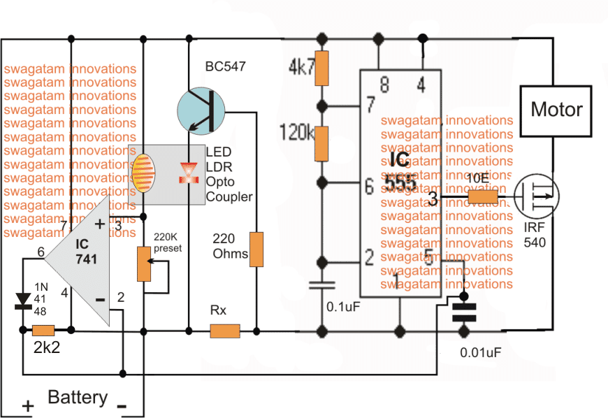
Using the Torque Optimizer for Treadmill Motors
The above explained torque optimizer circuit for induction motors is intended for electric vehicles, however if you are interested to operate an ordinary high power DC motor such as a tread mill motor, in that case the transformer section could be simply eliminated, and the motor could be directly connected as indicated in the following diagram:
I am sure you would be having many concerned questions, so please feel free to put them forth through your valuable comments. All your related queries will be answered at an earliest


Questions & Answers
Hey there! I’m looking to recurcuit my washing machine into an electrically charged water flow with a tankless point of use water heater. I want to connect the 2 directly together. Any ideas boss?
I’m trying to make a 12-48v 20amp pwm dc motor speed controller with a soft start function.
Kindly help me bro in this diy project. I will be grateful
You can try the following circuit. For soft start, just increase the value of C2 to 470uF.
And what about the pwm speed controller of 20a
PWM speed control is done using RV1, please see the figure which I provided earlier.
Please if I want to modify your automatic torque optimizer circuit for induction motor with in-built inverter , what are changes to make in terms of value of the components used in your circuit.
The capacity of motor I’m looking at 2.7hp,Rpm 4000,230v but I’m looking at reducing the Rpm to 1,500Rpm and what value to the current resistor Rx? Please guide me with the modified circuit
Thanks in advance
The above circuit is for increasing the RPM when load increases, it is not for reducing the RPM
If your requirement is reducing the RPM then you can simply use a triac dimmer switch kind of circuit.
How do I Use automatic Torque optimizer circuit ? Do I connect relay at the second circuit and use 230vdc at normally close connected the positive of the treadmill motor
Pls help with modified circuit
Please explain your need properly, I cannot understand it! If you switch OFF power, motor speed will come down.
Do you mean your motor should have an average speed lower than the maximum speed, by switching the relay ON/OFf?? In that case why not use a light dimmer circuit and adjust the knob to some fixed predetermined level.
Thanks sir,
I want to maintain a constant speed of 230 volts dc motor ,2.7Hp .even when switched off and on back let it maintain the set speed.please can you help me withthe working circuits diagram for.
If you switch OFF power there will be a lack of voltage and the speed will come down, there’s no way to keep it constant unless a UPS is used
Please sir, i need automatic speed controller circuit diagram of treadmill motor with specifications 230Vdc, 2.7Hp with 2 wire, red and black color code , permanent magnet.
I can maintain constant speed
Torque optimizer for induction motor circuit, what is the value Rx of current limiting resistor ? And if i voltage treadmill of 230vdc, 2.7hp is used; should use the first circuit with transformer, rectified the output and use?
For 230V DC motor you must use the second circuit. You only have to isolate the motor upper positive wire and connect it with the 220V DC, and connect the circuit side with a stepped down 12V
Thanks for quick response to my question, but one aspect is left un answer.
The question is how do determine the value of current limiting resistor of 2.7horse power treadmill motor of 230vdc in your automatic torque optimizer of electric motor circuit diagram.
The above circuits are for battery operation so it won’t suit your requirement if you want to operate the motor from your mains AC 220V socket.
Instead you can simply use an ordinary light dimmer circuit as shown below:
https://www.homemade-circuits.com/2012/04/how-to-make-simplest-triac-flasher.html
Sir, i have used dimmer switch to control before but the limitation is putting off the mains and left the nob at the constant speed, when switch on the mains the speed would’nt maintain the setting voltage.
Please, if your torque optimizer can modify to suit my requirement. What is the value of current limiting resistor Rx?
Emmanuel, if you want to use your motor with your home 220V AC then the above designs cannot be applied or may be one of the designs will need to be modified accordingly.
respected sir i read your posts on a regular basis and am always wating for your new posts
i own an embroidary shop and there are large power cuts in our area ie kashmir for which i use brushed dc/ac 230v motors run via an invertor but the problem is that there is lot of wear n tear of the armiture and it losts only about 6 months.
now i request yourself that is there any way to convert the brushed into a brushless one without causing any significant change in its wattage.
eagerly waiting for ur reply
Mudasir, you cannot convert brushed into a brushless motor because both work on entirely different principles. For a BLDC your will need a BLDc driver and motor and then configure it with your embroidery mechanism. There are many BLDc drivers and circuits in my website from which you can choose one and make at home, or even better buy a set from an online shop, buying will be much safer than building, if you are a newcomer in these matters.
Thanks Uday, yes the principle could be implemented for 3 phase motors also but the design could get much complex and elaborate than the above shown design