A welding machine is an electrical device which is able to generate a very high current at relatively low DC voltages. This high current output can be suitably used for creating the intended welding arcs and welding joints. The welding joint is created by fusing the welding rod on the joint area through a high current shorting generated by the welding machine.
A small welding machine can be built using a few ordinary 5 amp transformers and a few high current bridge rectifiers. I have explained how to do it.
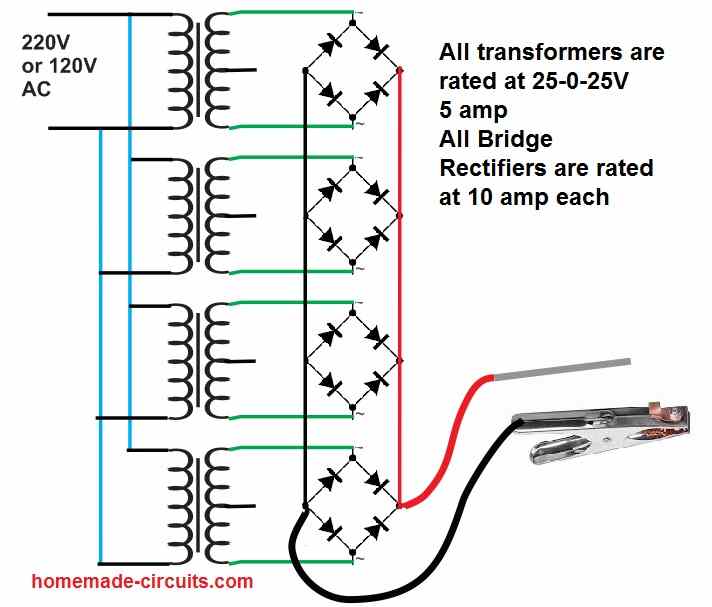
As shown in the following figure, we have used 4 nos of 25-0-25V 5 amp transformer in parallel to generate a reasonably good 20 amp current for the welding purpose.
This is recommended for small welding joints only.
The secondary of the transformers can be seen connected with high current bridge rectifiers in parallel.
The bridge rectifier convert the AC to DC and additionally boost the 25+25 = 50 V into a higher peak level of 50 x 1.41 = 70 V
So overall the output of this small welding machine circuit is able to generate 70 V at 20 amp which is equal to 70 x 20 = 1400 watts of power, enough to create strong welding arcs over small joints.
The bridge rectifiers must be rated at 10 amp each.
Either you can use 10 amp diodes to build the bridge rectifiers or you can ready made 10 amp bridge rectifiers modules for the assembly.
Using Capacitive Method
Caution: The following capacitive welding circuit is extremely dangerous to touch since the entire circuit is not isolated from mains AC and therefore it strictly not recommended for welding purpose.
Read it only for educational purpose and for gaining knowledge about a capacitive high voltage high current generator circuit.
A homemade small scale welding machine circuit is what most of the new hobbyists and mechanical engineers would be looking at for solving their occasional work bench metal welding jobs.
A mini welding machine without using complex circuitry could probably be built using a capacitive power supply as shown in the following diagram:
CAUTION: The mini welding machine circuit shown below is not isolated from mains and has the potentials to kill a person within seconds, therefore extreme caution is advised while handling this equipment in the powered condition.
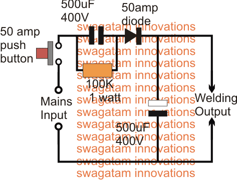
The idea shown above is an ordinary capacitive power supply circuit incorporating extreme capacitors in terms of their values.
Circuit Operation
At the input side we can see a formidable 500uF/400V capacitor, while on the output side also a similar rated capacitor can be seen positioned for reinforcing current.
The most basic parameter essential in a welding system is a high current, so that an extremely high temperature can be formed at the short-circuit junction, over the metal joint in question.
This high current generation can be achieved either by using a high watt transformer or an SMPS version of the same which I have explained in the first paragraph.
A transformer could be too bulky and heavy, while the SMPS circuit too complex for the newcomers, the only alternative way to achieve the high current welding through a relatively simpler design is perhaps by employing the high current capacitive power supply as shown above.
The 500uF/400V capacitor can be expected to generate bursts of current upto as high as 36 amps @ 220V, and reinforced with the complementing output filter capacitor this current can be expected to do some serious welding actions.
You can verify the above mentioned specs by using the following two calculator software:
The shown push button enables the user to achieve the welding job through shorts bursts, and not through a continuous arcing, which can be dangerous, and anyway is not recommended in welding operations.
The input 500uF/400V capacitor looks massive and it might not be readily available in the market, therefore this can be built by using 500 numbers of 1uF/400V PPC capacitors wired in parallel, this could occupy some space, but still the method is easily achievable.
Use Non-Polar Capacitors
This capacitor needs to preferably a non-polar capacitor, however since a diode is positioned in series means an electrolyte capacitor could also serve the purpose without issues.
The second capacitor at the output side can be an electrolytic type for sure.
For more current, the values of the caps could be increased to higher limits, that's the only parameter that needs to be focused on.
Advantage and Disadvantage
The advantage of this circuit is that it is small, cheap, and can be quickly built and used. The disadvantage is that it is very dangerous since there may be AC voltage at the output, therefore you will have to handle the whole system wearing rubber hand gloves.


Questions & Answers
Hi dear,
thanks for your best site,
Inpute voltage is 220 v? How can i use it ?like a welding machine to connect output?
Can melt Iron?
Thank you
Thanks Ali!
This circuit won't melt iron but join iron with the help of welding rod.
just connect the iron which needs to be joined with one of the output terminals, and the other output terminals with a welding rod, now touch the welding rod end at the point on the iron which needs to be fused…
Thanks Swagatam,
input is 230 V AC?
560uf 450v can i use?
what is the model 50amp diode?
50 amp push is a fuse?
thank you
yes will do.
50 amp diode is required for rectification.
the 50amp push is a push button which is required to be pushed and released while operating the power supply
Hey there,, I have a 470uF 250v cap,, can I use it?
Also what is the component no for 50A diode.? I have 5A diodes, can I put 10 in parallel to achieve 50A??
470uF/250 can be tried and will work as long as the input voltage does not exceed the 250V mark.
please search online regarding "50amp diode" you will be able to find a suitable one.
5A diodes in parallel will not help, and is not recommended
Hi sir,i need to show me how to step down 230VAC/2A to 150VAC/2A
You should put the 230v line wire on top of the step, and depending the number of taps each one will have a specific voltage drop (230v/no.of tapping). The last one is at the lowest level and should be connected to ground. The output you take it from the desired step and the ground.
Hi tun, I do not have asn SMPS version at the moment, however you can build an iron core based auto-transformer for the achieving the results
Hi sir please show how to make a 0-40v 0-3a smps
you can try the following concept
https://www.homemade-circuits.com/2017/06/12v-2-amp-smps-circuit.html
the Rfbb can be changed for getting different voltages at the output
Pls sir,is there any chances of electrocution as this circuit is not isolated with transformer.
yes definitely there is…even in transformer based welding machines you will have this danger
HI SWAG how to make this as adjustable current
Hi dennis, you can put different ranges of capacitor from 100uF to 500uF and add a selector switch to chose from them….
sometimes I hear electronics student say their capacitor exploded, though I never encountered such a situation but I really want to know the cause and how to prevent that from happening. am referring to the capacitor used in transformerless power usually connected in parallel with resistor in AC lines.
Capacitor will blow when the the supply voltage across its terminals exceeds the printed breakdown voltage value. In transformerless power this may happen due to sudden current surge when the capacitor is unable to stop the rise in voltage and bursts, a resistor and zener network will normally prevent this situation.
thanks a lot
what is the used of the capacitor the one in series with the mains? if its only function is to provide small constant current then why don’t we use a fuse instead?
Abba, fuses are not designed to suppress current they are designed to blow off as soon as the rated current is exceeded through them. A Capacitor cannot be compared to a fuse
thanks a lot for the reply
Sir, Can you please give me a simple transformerless welding inverter circuit with 230v AC input for arc welding of small jobs, brcause in the above circuit description, it is mentioned for short burst of current and not for continuous arc welding.
Regards,
Satish Naik
+91-9590018250
Satish, an SMPS welding circuit can be quite complex, I do not have an easier version at this moment with me.
Sir, then can I use the above circuit (Mini Welding Machine Circuit for Small Welding Jobs) for small welding jobs?
Regards,
Satish Naik
Yes you can try it, if the power is not sufficient you can add more capacitors in parallel
Thanks, I will try it.
Regards,
Satish Naik
I made an arc welder off 2 microwave transformers. I love the output (but can’t tell the exact amps).
What I’m looking to do I see make an amp-regulator that would enable me to comfortably weld thin automotive sheet metal. Please help me with a circuit layout to add to my welder and achieve the results.
Thanks.
The only way to limit current in a high current AC system is by adding resistive load in series. You can probably add a 2000 watt heater coil in series, or as per the specs of the welding machine
Capacitors name please
Mini welding machine
2 capacitors 500uf 400v
1 capacitors 500uf 400v ppc
1 capacitors 500uf 400v none poler capacitors
1 capacitors 500uf 400v electrolyte capacitors
Please tell me two capacitors name
How to make 50amp diode
Capacitors don’t have names, only specifications which you have already mentioned in your comment. The input side is non-polar and the output side is polarized.
Hi! What’s the current and voltage output at the welding point?
220V, 25 amps for a second
Hello again! I am intrigued by the simple welding circuit. You say I could use a polar capacitor in place of the non polar, since there’s a diode. Can I connect the negative of the cap to the anode!
Yes you must connect the negative of the capacitor with the anode of the diode
Can you manufacture some pcb’s …qty 10+. Can you do that from a schematic? Without me having to upload a member file?
sorry I don’t manufacture PCBs at the present moment. You won’t need a PCB for this simple design, you can do it over a stripboard
I like your straight forward down to earth articles, thanks for sharing. I have a problem I sure you can help me with. I need to build a high-voltage DC power supply which will be used as an arc generator. (Not for welding, more like a tesla generator). My input is 117VAC RMS and I have a Hammond 733A transformer which gives me 2.5kVAC CT. My question is what diodes should I use to make my bridge rectifier? The power supply output will be connected to 5 high-voltage computer controlled switches to tungsten rods around a central tungsten ground rod. Any given switch will be active for 10ms or less at any given time.
The diode specs will depend on the load current. For example if the current drawn by the load is 50 amps, then the diode will also need to be rated at 50 amps (in this case because the duration is only 1 ms)
good time to you sir, please the input and output voltage please
hello alkali, input can be 120V AC or 220V AC, output will be = input AC x 1.41.
Dear sir
how to add a capacitor discharging circuit for a battery spot welding machine’s out put ? can you post a diagram when you free.
Dear Ajith, what is the maximum voltage specifications that you require for the applications?
Input 220 Vac
Out put 3-6 Vdc
Current 1000amps to 3000Amps variable.
Thanks for reply.
Ajith
6V, 3000 amps is huge, I do not have an SMPS circuit for this specification at this moment.
Hi sir,thanks for the wonderful post I have few questions regarding this welding machine
1.i have couple of 6A10 which I intended to connect them in parallel to achieve the specified current rating but you mentioned in the comments that connecting diods in parallel will not help, pls I need to know why doides cannot be connected in parallel to maximize current.
2.what are the minimum voltage and current required for a well functioning welding mechine? because I have a 5kva stablizer transformer ,can rewind it?if yes,what would be the output voltage and current?
3.is the above circuit a d.c or a.c mechine?
4. Can both the two capacitors be electrolytic polarized capacitors?
Pls sir do not mind me asking too much questions am just a newbie.anticipating your response sir.thanks again for the good job.
Hi Muhammad,
1) diodes cannot be connected in parallel because semiconductor devices do not have exactly identical characteristics and all the devices may not conduct together causing one of them taking the entire load at once and burning. You can add a 1 ohm 1 watt resistor in series with each diode and then add the combination in parallel.
2) I do not have an expertise in welding so cannot suggest much about their specifications.
3) The above circuit is DC, but you can also use the AC version, simply by removing the diode and the filter capacitor.
4) The left side capacitor cannot be polarized, it must be a non-polar capacitor.
I appreciate your response sir thanks again
You are welcome Muhammad.
I like it but I fear to atemp bcz u said it is dengerious.help me with another circuit that can be safe when welding.
The other option is using a large transformer with high current output DC
If I used this circuit, do i expect to connect it direction to the welding ROD like 2.5 MM , use it as regular welding machine for continues welding as MMA weld machine , is it rated as 50 AMP weld machine ?
It can be used for continuous welding at 25 amp current.
But the problem is that this circuit is not isolated from mains AC and is very dangerous to touch…. therefore the welding operation will need to be done by wearing gloves.
Therefore I don’t recommend this circuit. Instead using transformer based design is a safer option
Well done.it perfect. Pls help me out cna one convert a refrigerator compressor core winding to a wielding machine as shown on some youtube channel
Thank you for your question, however I am not sure how this can be done…will need to be investigated deeper.
Can I use ups transformer for this project
Computer ups transformer
Each transformer has 12v
2 transformer connect in series and 2 transformer connect in parallel
It will work and weld small job
You can use it, but the connection should be in parallel only as shown in the first diagram.
Why is the connected in parallel
To increase current capacity.
Hi Mr. Swagatam;
I will use 12V 60A car battery for spot welding the nyaf cable (multicore cu cable diameter is about
1 square mm) so could you please advise the necessary minimum ideal output voltage and current.
Hi Suat,
Sorry, I have no idea how much voltage and current might be required to generate sufficient spot welding heat for welding nyaf cable???
I think spot welding might require big short bursts of current which can exceed 60 amps
Sir, first thank you.
Does series transformers also pose voltage danger?
Hello Jonah,
yes, if it is connected to mains AC then series transformer can also pose a risk of electric shock..