In this post I have explained a simple single phase jet water pump controller circuit using magnetic reed switch level sensor, and a set/reset circuit. The idea was requested by Mr. Nanigopal mahata
Technical Specifications
- I am your blog follower,, i searched all the blogs for automatic submersible pump controller but i can't understand which one is single jet pump controller circuit.
- Help me out with a circuit diagram where I can use two 12 volt 10 amp relay (single pole single throw) , and two reed switch(for level sensing).as the water tank full jet pump will automatic off and vise versa.
- Also mention the transformer rating to control the whole circuit, and mention the ic which one is suitable.. as soon as possible.
The Design
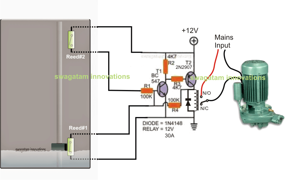
The diagram shows the proposed single phase water jet pump controller circuit consisting of water level sensors using reed switches, and a transistorized set reset latch stage.
I have already explained how to make reed switch based water sensors also called float switches, you can refer the linked article for a detailed info regarding the same.
The transistorized latch circuit is made through a couple of transistors which are designed to latch and delatch in response to the relevant reed switch operations.
The two reed switches as shown in the diagram are positioned to sense the high/low water levels, when the water level is low, the magnetic float is held near the lower reed switch, and when the water level reaches the top of the tank, the magnetic float approaches the upper reed switch. During both these occasions the relevant reed switch is actuated.
At the upper water level, the upper reed switch closes which in turn latches the transistor latch circuit, activating the relay.
The relay contacts then switch ON the connected single phase jet water pump motor.
The jet motor begins emptying the tank, until the water level reaches the lower threshold which actuates the lower reed switch, quickly breaking of the transistor latch.
With the latch disabled the relay is switched OFF. This action immediately stops the jet pump motor, until the tank is filled again upto the top to initiate the switching cycle.

Questions & Answers
…. I mean reed#1 starts and reed#2 stops
I salute you for your good job unto us. I am Michael from kenya, how can I make this circuit to function vice versa? to fill this drawn tank from a borehole. When water drops to reed switch 2 the motor starts and when it reaches reed switch 1 it stops??
Thanks very much for liking my work, for getting the reverse effect in the circuit, you just have to swap reed#1/reed#2 positions with each other.
sir i have done sucessfully.. but i use the circuit model of semi auto control…. there i use a reed switch instead of the push button.. its work well,, but at upper level its take 3 to 5 sec to off the pump…. and hold the magnet there for 5 sec for discharging the capacitor…
I cannot see any capacitor in the circuit? which capacitor are you referring to?
sir i did everything, the power supply is made with a transformer and 4 1n4007 diod, and whatever i did that, i didn't connect direct 220v at n/o ,instead i connect there 12v dc.
and instead the jet pump i use there a led light.. is it wrong?
the output i get ,
1. as the magnet touch the upper sensor the relay activ and led on and vice versa.
at the lower sensor i didn't get any output
Nanigopal,
don't connect anything with the relay, you can confirm by listening to the relay clicking. Make the set-up as shown in the following diagram:
2.bp.blogspot.com/-KaxQesNmH9A/U9cglC_i64I/AAAAAAAAHu4/XS-uqmtWlrk/s1600/set+reset+circuit.jpg
pressing the upper push button should activate the relay, and pressing the lower push button should deactivate the relay.
Once this is confirmed then you can verify the results through reed switches.
if it still does not work then certainly there's some mistake in your connection or the parts
sir also tell me,, how i can test if the latch circuit will work properly or not…
Nanigopal, you can test it by touching and releasing the reed connections manually for a moment, this will latch and de-latch the relay accordingly
sir i can not understand the relay connection properly.. i use, JQC-3FC(T73)-1C-DC12V relay… and the transformer i use ratting 12-0-12 500 ma to energies the circuit…
problem is that the voltage (12v) dropped much and the relay doesn't work properly
To make this circuit you must know all the basics of electronics first, like how to connect a relay, how to make a power supply with transformer bridge rectifier capacitor etc….so unless you all these it won't be easy for you to succeed with this circuit.
you can refer to these articles for more info:
https://www.homemade-circuits.com/2012/01/how-to-understand-and-use-relay-in.html
https://www.homemade-circuits.com/2012/03/how-to-design-power-supply-simplest-to.html