The following multi-function water level controller circuit post is based on the suggestions expressed by Mr. Usman. I have explained more about the requested modifications and the circuit details.
The Circuit Suggestion:
The concept of this circuit looks good. May I suggest a couple of other desirable features?
1) To protect the motor from potential overheating (or as a safety feature) can u add an automatic shutdown timer? If the motor is running for one hour (or 1.5hrs or 2-hrs) and the water level does NOT reach the level-sensor, the motor should be automatically stopped. Of course, it can be re-started manually by pushing the start button again.
2) Can the motor be manually stopped at any time? For example, what if one wants to water the lawn (or wash the car) for a few minutes using high pressure water directly from the motor?"
Thanks very much!
Your suggestions are interesting!
I think I have discussed these issues in this article.
However instead of a timer I have used a temperature sensor circuit for tripping the motor if it starts getting hot.
The motor can be manually stopped by shorting the base of T3 to ground. This can be done by adding a push button across these terminals.
So the upper push button may be used for initiating the motor while the lower button may be used for stopping the motor manually.
Thanks Swagatam for a prompt reply. I've found another circuit on your blog (April 20th post) that is closer to what I have in mind.
I want a slightly different control logic in the above circuit:
Motor START Logic:
Manual push button (already implemented)
Motor STOP Logic:
1) Water level reaches a pre-determined level (as implemented in April 21st post), OR
2) A pre-determined time has lapsed (e.g. 30, 60 or 90 mins, this requires a long time-delay/counter), OR
3) Manual stop (manual override), OR
4) Power faliure (load shedding), this is implemented by default!
So I guess, the STOP logic (1, 2 and 3) can be configured to the base of T1 (in your April 20 post) and it should work. Pls comment, and if you have time maybe you can make a new post!
Thanks
Usman
The Design:
Let's analyze the above requirements and check how they have been implemented in the following diagram:
1) Water level reaches a pre-determined level: Point A and B may be appropriately fixed inside the tank for regulating this function.
Since point B is situated at the bottom of the tank, remains connected with the water permanently, now as the level rises and comes in contact with point A, the positive potential from point A connects with point B, which instantly reset pin#12 of the IC, switching OFF the relay and the entire system.
2) A predetermined time has lapsed: This feature is already present in the below given circuit. The timing outputs can be increased to any desired extents simply by increasing the values of P1 and C1.
3) Manual stop (manual override): This feature is actuated by SW2, pressing which resets the IC pin#12 and the entire circuit.
4) Power failure (load shedding): During a possible power failure or instantaneous power "blinks", the IC needs to be supplied with the required supply voltage so that the timing does not get interrupted. This is very simply done by adding a 9 volt battery to the circuit.
As long as normal power is present, the cathode of D3 stays high keeping the battery switched OFF from the circuit.
The moment power fails, the cathode of D3 becomes low, providing a way-in to the battery power which smoothly replaces the supply to the IC without causing any "hiccup" to the counting operation of the IC.
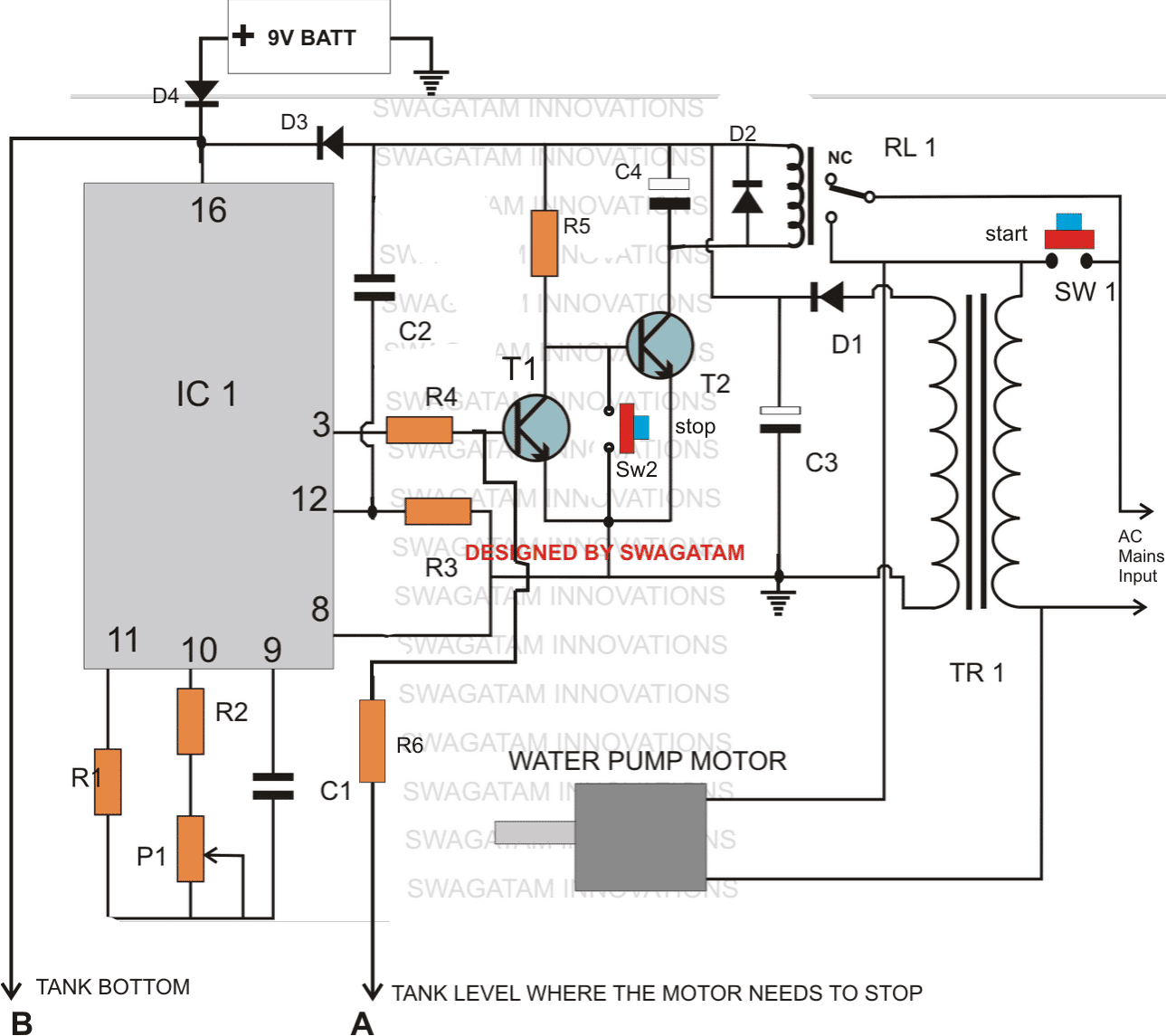
Parts list for the above explained multi-function water level controller circuit
All resistors are 1/4 watt 5%
- R1, R3= 1M,
- R2, R6 = 4K7
- R4 = 120K
- R5 = 22K
- P1 = 1M preset horizontal
- C1 = 0.47uF
- C2 = 0.22uF disc ceramic
- C3 = 1000uF/25VC4 = 100uF/25V
- D1, D2, D3, D4 = 1N4007,
- Relay = 12V/SPDT
- SW1,SW2 = Bell push type of button
- IC1 = 4060
- T1, T2 = BC547
- TR1 = 0-12V/500mA
- BATT - 9V, PP3
Water level buzzer indicator circuit
The following circuit of a water high level and low level indicator circuit was requested by Mr.Amit. Please read the comments given below to know regarding the exact specs of the requested circuit.
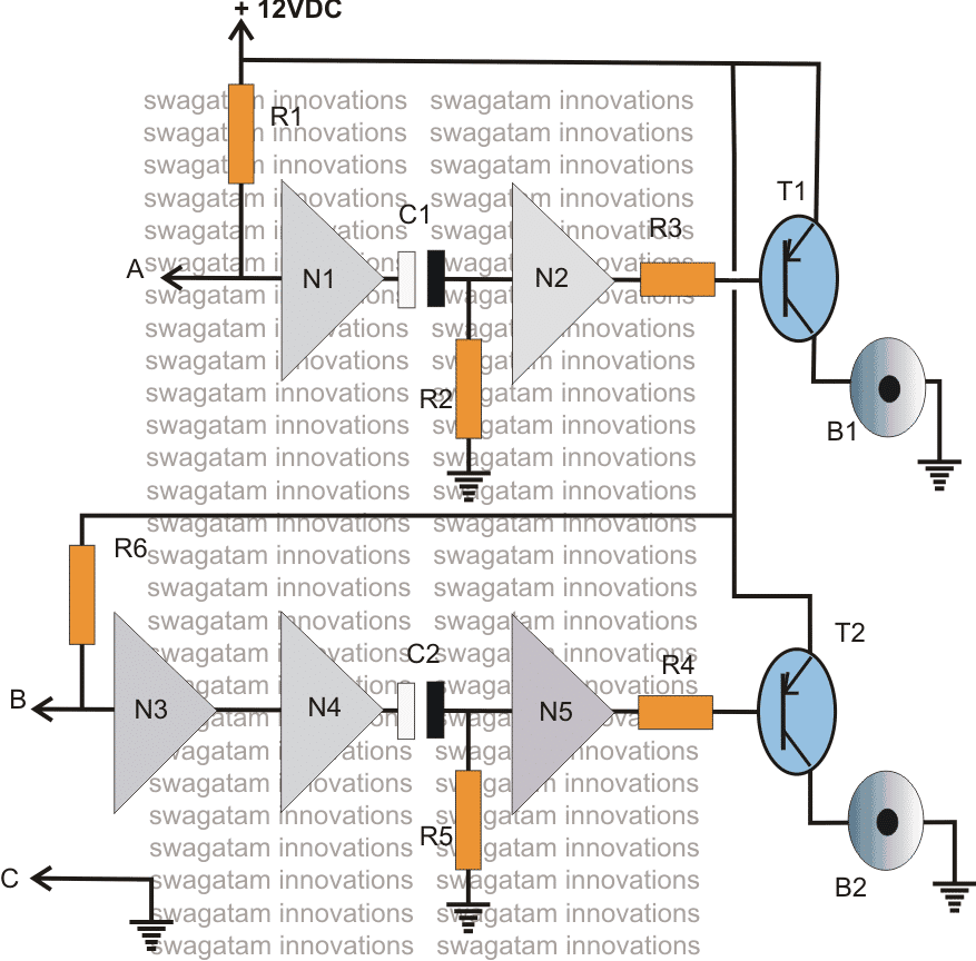
Circuit Operation
The above shown water high and low level buzzer indicator circuit may be understood with the following points:
Point C which is connected to the ground or negative of the supply rail is kept immersed in the tank water at the bottom level such that the water present in the tank is always held a logic low.
Point B is the low level sensor point which must be positioned near the bottom of the tank, distance may be set as desired by the user.
Point A is the high level sensor, which should be held somewhere at the top of the tank as per user preference.
When the water level reaches under the point B, point B goes high due to R6, making the output of N4 high and consequently producing a low at the output of N5....the buzzer B2 starts buzzing.
However in the meantime C2 starts charging up and once it's fully charged inhibits the positive potential at the input of N5.....the buzzer is switched OFF. The time for which the buzzer remains On may be determined by the values of C2 and R5.
In an event the water reaches the top level of the tank, point A comes in contact with the low logic from the water, output of N1 becomes high and the same process is repeated as explained above. However this time B1 starts beeping, only until C1 gets fully charged.
Five gates from the IC 4049 have been utilized here, the remaining one unused gate input should be grounded for maintaining stability of the IC.
Parts List
- R1,R6 = 3M3
- R3,R4 = 10K
- T1, T2 = 8550, or 187, or 2N2907 or similar
- C1,R2 = to be selected for setting up buzzer on time
- C2,R5 = to be selected for setting up buzzer on time.
- N1---N5 = IC 4049
- B1,B2 = Loud piezo buzzers


Comments
Dear Sir,
I have seen your circuit recently Making a Multi-function Water Level Controller Circuit I feel it will be useful. I was using a relay module with a float switch to trigger the relay when water full but motor starts and stops until unless the float switch settled , that will burn the motor if continuously stats and stops. In this circuit I have not tried yet procuring IC CD4060 then I will try. I have quarry 1. that the power supply you have designed with one diode and a capacitor or a regulator power supply or a zener diode 9v can be used for the same ? No 2 if water touches the probe the motor cuts off completely or it fluctuate so that motor will start and stops continuously. i need a complete cutoff the motor as power supply will be in presence or any two relay version can be used. I need little clarification. your designed are great …
Thank you Nirmal,
The motor will stop permanently until the start button is pushed again, because when the water reaches point A, the left transistor is forced to activate, which in turn causes the right side transistor/relay to turn off and break the latch and the relay contacts settle at N/C shutting off the entire circuit completely.
Dear Mr. Swagatam,
You are doing great work.
Above mentioned circuit can fullfill my requirement,but instead of continous running of circuit during power failure I want that motor could not turns on once power failure occurs. Hence, submiserable pump requires some rest to wash its blades once it turns off by using of water available in pipe. And if circuit turns on instantly after power resumes, it will burn the motor. And I also add high/low voltage protection in it. How to achive that result?
Thank you Umar,
I think you can try the following concept for the motor:
https://www.homemade-circuits.com/simple-refrigerator-protector-circuit/
And for the high low cut off you can refer to the following article:
https://www.homemade-circuits.com/highly-accurate-mains-high-and-low/
Thanks for your replay.
Its seems both your links gives same results in term of high/low protection. which one is better for me in my earliar mentioned case???
second, If I made according to “https://www.homemade-circuits.com/highly-accurate-mains-high-and-low/ ” then how to achieve delay time requirement while power failure resumes?
The link gives the delay ON timer circuit, the second link shows the high/low protector.
Hi, does the above circuit have automatic ON function if the water level goes below low level? If yes means how it will work?
Because I require a circuit with automatic ON, OFF facility with timer. Like if the water level goes below low level means the motor should run and after predertermined (45)mins time the motor should off. Within that 45mins the water level reaches the high level (at 30mins) also the motor should off.
To implement the mentioned functions, you will have to modify the design in the following manner:
Remove SW1 and all it connections with the relay, and connect the transformer directly with mains.
take a Darlington NPN using two BC547, fix its base through a 1K resistor at the top water level position, where the cut off needs to be sensed, also make sure to use a 1uF capacitor across base of this transistor and the ground supply line.
after this connect the emitter of this transistor with base of T1 through a 1K resistor, and also connect its collector with the positive supply line.
Hi, i think the above circuit have manual ON and automatic OFF.
Could you please design me a circuit with automatic ON, automatic OFF and timer?
So when water goes below low level, the motor should get automatic ON and the motor should get OFF at 45mins or the water level reaches high(if tank is full within 45 mins).
Hi, I have already explained it in the previous reply….
Yeah, you suggested me to make a darlington and place the sensor at the top level where motor need to off but that is already implemented in the above circuit. In the above circuit also a Darlington and the top sensor is there to turn off the motor. I want the motor to ON when water is reached low level. If am wrong about the circuit means could you please explain.
yes it is already implemented, and it seems the automatic start can be difficult to implement in this design.
you will have to incorporate the following concept and attach a 4060 timer circuit externally which will switch OFF the relay after the predetermined time
https://www.homemade-circuits.com/how-to-make-simple-water-level/
for the timer you can use the first circuit from this article.
remove the transformer power supply and also the triac stage.
disconnect the R3 end from ground and connect it with the collector of the water level relay driver transistor.
and connect pin#3 with another BC547 stage with its emitter to ground base to pin#3 of 4060 and collector to the base of the water level relay driver transistor. make sure to keep the 1n4148 diode across pin#3 and pin#11
here’s the link for the timer article
https://www.homemade-circuits.com/simple-triac-timer-circuit/
Thank you sir . this helped a lot. But sir one more doubt here in this link-
1.bp.blogspot.com/-bGcwz6ySGw0/TwkZ1PwTEhI/AAAAAAAAAqQ/ZdaGCKNyBsk/s1600/Light+Switch.png
Is it connected to some sort of Controller as the marking shows some pin numbers or its an entire IC structure. And the one you told initially that darlington one which one you feel will be the best and most apt . 🙂
Thanks a lot sir. 🙂
when water is present across the input terminals of the first gate, the DC will pass through the water and make the input of the first gate high, which will in turn make its output low. This low will reach the inputs of all the connected parallel gates which will respond to this and make their output high. This high will trigger the transistor relay stage and switch ON the motor….
exactly reverse will happen as soon as water is removed from the sensor terminals, switching off the motor.
Sir one last thing please explain how these gates will work and provide desired output as m supposed to explain this asap. Thank you.
both are equally good, using a Darlington tramsistor makes the construction a bit simpler that's all…
Jack, the pin numbers given on the "gate" symbols are from the IC 4093, the transistor can be a 8050 or a 2N2222, its base resistor is 4.7K and the relay is a 12V relay.
P1 can be a 1M preset for adjusting the sensitivity of the circuit
you can feed the AC to the water controller relay and the motor through the following circuit for the overload protection:
https://www.homemade-circuits.com/2012/09/mains-ac-overload-protection-circuit.html
when the water bridges the shown metal conductors across the pipe its resistance goes down which allows the transistor to conduct and operate the relay.
yes a Darlington transistor is used for greater sensitivity.
logic gates can also be used as shown here:
1.bp.blogspot.com/-bGcwz6ySGw0/TwkZ1PwTEhI/AAAAAAAAAqQ/ZdaGCKNyBsk/s1600/Light+Switch.png
remove the LDR R1, and use its terminals as the water sensor across the pipe.
please explain all the features in detail so that I can understand the exact functioning of the required circuit.
hello jack, by start stop switch do you mean you want to include manual switches also for staring and stopping the motor by overriding the water sensor??
Because in the present set up the relay and the motor will get activated only while water is flowing out from the pipe, and stop immediately as soon as water stops pouring out from the mouth of the pipe
Hello Jack,
you can try the following circuit:
https://www.homemade-circuits.com/2014/10/municipal-water-supply-sensor-pump.html
it does not use CMOS ICs but would still work as efficiently.
Ok thanks Swagatam, I'll try this and see if I can do something to avoid the IC from counting when the circuit is switched ON.
OK, thanks!
Hi Swagatam, I am making this circuit with a slight change. I need to combine this with the wireless water level indicator. I have all that built up. My requirement is that the wireless indicator should be ON at all times to show the water level while I want all other functionality of this circuit – which is manual start and automatic stop based on either timer or tank full.
I can use 2 power supplies here – one to supply the indicator circuit and another to the controller circuit but I don't want to use 2 of them. Is there a way you can suggest. Another point to note is that the controller works at 5V while the rest of the circuit is on 12V. In fact I had converted this controller circuit to work at 5V but then couldn't get a 20A relay for 5V so I went back to 12V for this. Any help would be useful here. Thanks
Vijay
Yes that' correct, to rectify this I think we can try connecting SW2 such that when pressed either it short circuits C1 or R2/P1, that is either across C1 or across R2/P1, on doing this pin3 could be expected to go high, instantly locking the IC counting.
and pls note that SW1 is only for resetting a start… first time when power is switched ON, the motor would start without SW1 press, but subsequently after the timing has elapsed sW1 may be pressed to reset and restart the motor.
Sorry, please use this link instead for the modified diagram : s4.postimg.org/gb0nrslbx/Modified_Water_Level_Controller.jpg
I have omitted the deriving 5V across C3 via 7805 for simplicity.
HI Swagatam, Thanks for the suggestion. Although I mostly understand what changes you've suggested I am not able to see how would the circuit work. You've introduced a diode to latch the output once the timer is done with the counting which is okay as it would ensure that the relay is OFF once the timer time is reached. But how would the motor get started when I press SW1 which is not across C2? Wouldn't the timer circuit start counting itself when I supply power to it because PIN 12 is not high? Please explain this a bit. I have uploaded the modified diagram here : postimg.org/image/e3g9s011j/
Hi Vijay, you can do it in the following way:
Remove SW1 and short it's points with a link
break the link which was present between SW1 and the relay NO contact and the motor wire.
After this connect a diode across pin3 and pin11 of the IC, cathode to pin11.
bring SW1 to a new position that is parallel with C2.
That's it, it's done now you can use the DC output across C3 to power your wireless system but through a 7805 regulator stage.
thank you sir for the reply….. but your answer is not suitable for my need…. i want to design a led demonstration of the solar planet system…. so in each orbital path leds should be arranged in such a way that all the LEDs in that path shouldn't blink simultaneously, in other words one after another…. if we are gonna implement the current design in this blog for this project, it will lead to the use of 8 separate CD4017 ICs and their components…. that is why i had initially asked for a LED flasher which is to be implemented to a series connected LEDs
Arun, yes you'll have to incorporate 8 separate 4017s for the different paths…you can't get the feature in one IC, or you'll have to resort to a microcontroller circuit for getting it one chip.
Hi Sawagatam,
can u make a circuit similar to the one in the link given below using 4060 with motor timing & water level controller(i.e.,)motor should run for 1 / 1.5 / 2 ,etc hours depending on the intervel set or till water reaches up probe in given link.
Circuit link : https://docs.google.com/file/d/0B8LpX4NzfdkIMm51eVdlWWUyOWM/edit?pli=1
here motor starts only when water level goes below low probe & motor stops when it reaches up probe.
Hi Prabhu,
I already have a similar circuit in my blog, which is even more accurate since a CMOS IC is involved
https://www.homemade-circuits.com/2011/12/how-to-make-simple-water-level.html
this crkt working. here motor starts automatically if water level goes below point A itself(not point B (i.e.,)even if water is 1% below point A motor starts but water above point B).
i want a circuit which switches on motor only when it reaches below point B(lowest point)
the first circuit will not start once it's switched OFF until SW1 is pressed, so something may not be correctly connected in your circuit.
for an automatic start and stop you can try the following design, it will provide both upper and lower limit protections:
https://www.homemade-circuits.com/2011/12/how-to-make-simple-water-level.html
I have used many type of brass/steel screws for the purpose of sensor,after sometime it will be rusty,now someone suggest put a floater switch as a sensor,can you suggest is it working on your ckt,in the floater switch there are three terminals,may i know the wiring.
Thanks
Prikshit
Chandigarh
if you can provide me the 3 lead specification of the float switch then surely I can show you the integration method with my circuits.
I guess one lead may be assigned to the supply positive or negative, while the other two may be responsible for switching this negative or positive via reed relays in response to their specific water levels…..you may confirm this for further discussion.
Requests can be posted through comments only, exactly as you have done.
I have understood your requirement, I will try to update it soon in my blog and inform you.
Sir can i use a 12V 10 A relay for a half hp pump?????
I have found in some articles that the initial driving current goes to 6-7 times the running current for a motor. So eventhough mine is a HALF Hp one drawing nominal current of 380W/230V= 1.6 A, it may have 9.6 to 11.2 A of starting current.
Also i have noticed in my relay the specifications written which i am giving below
50/60 Hz
7A 250V ~ | 10A 125V AC
12A 125V — | 10A 28V DC
I am not at all familiar with electronics but i a m very interested to do simple projects like this. I couldn't understand the exact meaning of the specification written here. So please help in this issue?
May i have to change the relay or not?
Sorry for the bad english
Hello Kajal,
Yes you will have to replace the existing relay with a 30amp relay or you may also try using a triac instead…..a BTA41/600 could be tried.
Sir will the battery used in the first schematic be drained all the time by the ic and the incorporating circuitry????? Even the mains is present????
As long as mains power is present battery will not drain, when mains fails the IC will consume 5mA, and the relay 40mA (when in ON position) from the battery
Thanks for ur kind reply sir
Hi Avijeet,
You can any value above 10k for the 1M position and get any desired timing output.
Alternatively you can also experiment with the capacitor for the same.
Use the outer taps of the trafo and connect them with the bridge or whatever rectifier stage you are using, leave the center tap alone, it won't be required.
Thanks sir,
I had made the corrections and now it is working fine.
#Sir want to ask u that i had to drive the circuit only for 10 to 20 min so 1m preset is giving huge fluctuations to set it for such a small time period.could i reduce the value of 1m preset without changing capcitor value.
#how could i use 6-0-6 value trfo to get 0-12v for above circuit.
Thanks
Lead atoms would be tightly bonded inside the solder metal so there's little chance of it getting dissolved, and even if it does it will be in negligible quantity. But anyway safety is always first so it's better to avoid it and find some other similar yet safe alternative.
Regards.
Thanks for your reply.
I think there is a strong possibility of lead poisoning if solder comes in contact with drinking water. Already there are thousand other things which could kill us and I don't think we should add one more 🙂
I think some kind of contactless sensor should be a safe bet. I read somewhere people using sensors from automatic washing machines which could measure water pressure. But these sensors will surely be difficult to find. I'll keep scratching my head for more ideas.
Regards
Raman
Hi Raman,
Thank you very much!
This question has been asked by many readers here, and as per my thinking I have suggested them to use use brass terminals tinned thoroughly with solder wire. According to me tin will remain unaffected from corrosion, but I am not sure about algae or other such formation on its surface which probably has no remedy.
Using frequency with the sensors is one option but since the receiving sensors are passive we cannot introduce frequency in them,so this option doesn't hold good either.