While using amplifiers, we sometimes experience this very annoying thump sound, popping up in loudspeakers whenever the amplifier is switched ON or OFF.
This normally happens with amplifiers that are of low quality or lack the feature of a thump eliminator circuit built-in in the amplifier.
The thump sound in loudspeakers can be not only annoying to the ears of the user, but it may be also equally detrimental to the speakers life, which might eventually at some point of time burn the speaker coils and cause a permanent damage to the loudspeakers.
In the proposed loudspeaker thump sound eliminator circuit, once installed and wired in an existing amplifier, will ensure that the loudspeakers connected with the amplifier never encounters this thump like pop sound.
Why the Thump Sound Happens
We know that every power amplifier involves a series capacitor connected with the loudspeaker.
This series capacitor may be present either directly connected in series with the loudspeaker or connected across some other stage of the amplifier.
When power is switched ON, this capacitor causes an initial short circuit for the loudspeakers causing a loud pop sound to appear, which slowly decays away as the capacitor charges up fully.
The reverse happens when the amplifier is switched OFF, when the capacitor discharges through the loudspeaker again causing a loud thump sound through the speakers.
How the Circuit Works
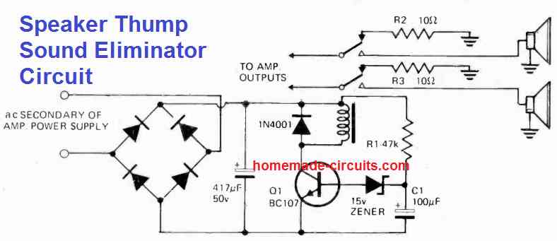
As can be seen in the figure above, the loudspeaker thump sound eliminator circuit is actually built around a delay ON timer circuit.
The transistor Q1 and the relay together with the capacitor C1 provides a delay of about 2 seconds before the relay is switched ON.
The relay can be seen wired with the loudspeakers, the amplifier and 10 ohm resistors.
The power to the transistor relay timer circuit is derived from the amplifier power supply itself.
When power to the amplifier is switched ON, the speaker remains disconnected initially since the relay does not switch ON due to the delay ON timer action.
During this time, the capacitors inside the amplifier quickly charge through the 10 ohm resistor, connected with the N/C contacts of the relay.
Once the initial delay is over, the transistor conducts and powers the relay, which in turn connects the loudspeaker with the amplifier.
The loudspeaker now makes no thumping or popping noise, since the amplifier capacitor are already charged up and the shorting of current to the speakers does not happen. In this way the thump noise is eliminated from the speakers.
The above working takes care of the amplifier switch ON issue, however when the amplifier is switched OFF, the transistor relay switches OFF quickly, preventing the amplifier capacitors from discharging through the loudspeakers.
Instead, the relay contacts now connect them back to the 10 ohm resistors so that the internal capacitors can now discharge safely through the 10 ohm resistors.
Due to this again the thump sound is eliminated from happening during the power switch OFF.
Using IC 555
When a power amplifier is switched ON, it normally experiences a large DC offset at the output until the DC-blocking capacitors are slowly charged up.
This gives rise to an audible 'thump' sound on the speakers that can be quite harmful to the loudspeakers.
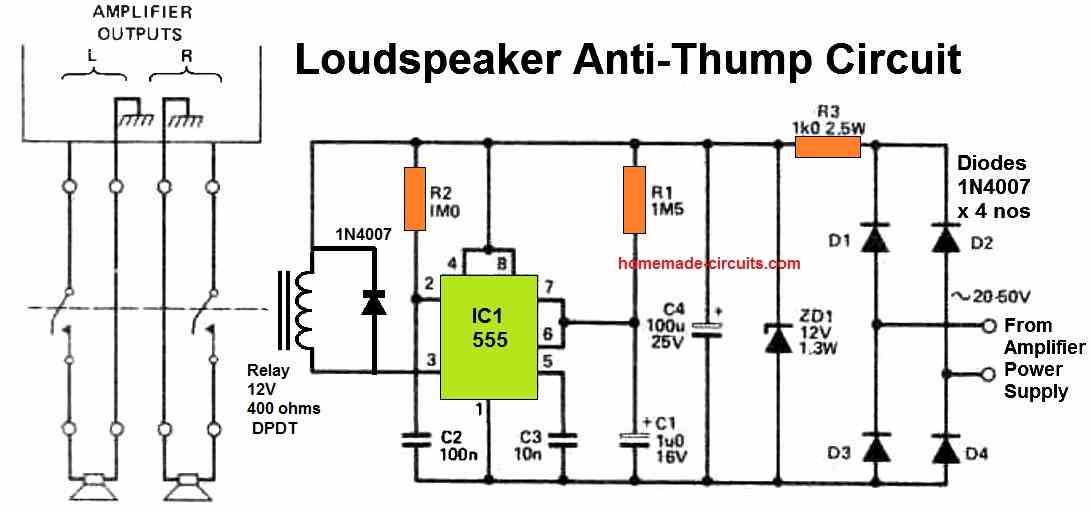
To solve this issue, this proposed anti-thump circuit introduces a delay between turning on the power switch and connecting the speakers to the amplifier.
Of course no delay is caused while turning off the amplifier which again avoids the thump sound during power switch OFF.
IC1 functions as a 555 timer in monostable mode, triggered by a negative-going edge signal provided by R2 and C2. During the output pulse, the IC1 output goes to the negative rail.
This allows the relay to be connected between the output and the positive side.
The delay time can be calculated using the formula 1.1 x C1 x R1, which provides a delay period of about 4 seconds as per the given component values.


Comments
How can I adapt a 555 timer circuit like this for speaker thump elimination from the 3.5mm headphone output of my computer the RCA inputs on a set of self powered studio monitors?
Eliminating thump for a 3.5mm jack connection can be difficult, because while you are removing the connector the amplifier is already in the powered condition, so the thump sound cannot be eliminated.
You can turn off power to the amplifier and then remove the connector…
can you teach me how to design a dc power supply
Sure, the following article can help you:
Designing Simple Power Supply Circuits
Good night
What is the power of the 10 ohm resistor
Grateful for the attention
It can be a 5 watt resistor for amplifiers below 300 watt
Good Morning
Grateful for the answer
You are most welcome!