This Guitar Jammer circuit I have explained below enables you to jam out to your favorite songs from your cellphone or computer.
You can mix an external audio track with your guitar sound, then use headphones to listen to the blended result.
Imagine playing note-for-note copies of legendary guitarist's riffs and exchanging scorching pentatonics, "hammer-ons," and "pull-offs" with the best players. By Sudhir Roy.
You would be surprised by the outstanding "presence" obtained from such a basic design once you've turned on the circuit and experienced the sound.
The fact that the headphones cancel out background noise from the room is one of the causes of this.
As a result, the combined output covers you with music, giving the impression that the guitar track you are playing is actually from one of your favorite albums.
Circuit Description
The following figure displays the guitar Jammer circuit. A 9-volt battery, B1, serves as the circuit's power source, while S1 is the power button.
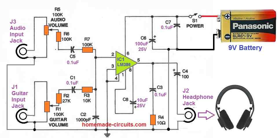
IC1 is an LM386 audio amplifier. Capacitors C6 and C7 are placed to provide decoupling for the IC1. With the shown configuration, IC1 has a gain of 200.
This much gain is perfect for this application and secure for your ears, thanks to the bypass capacitor C8, connecting pins 1 and 8!
J1, a common 3.5mm jack, receives the guitar input. Following that, the signal is routed to potentiometer R1 to adjust the volume.
The guitar signal leaves the wiper of R1 and travels via capacitor C1, resistors R2, and R3.
These resistors offer the best possible isolation between the external audio input and the guitar's volume control. As a result, the controls on the guitar only need minimal loading.
To avoid RF burst at the input, the guitar signal is therefore fed to pin 2 of IC1 and connected to shunt capacitor C2.
The jack J3 receives the audio input. Capacitor C5 serves as coupling, while potentiometer R5 is utilized to adjust volume.
Resistors R6 and R7 make sure that the guitar audio channel at pin 2 never switches to ground level.
The resultant mixed audio is produced at pin 5 of 1C1. This mixed audio is supplied into a standard Zobel shunt system built using R4 and C3.
At increased volume, this Zobel network keeps the audio output perfectly stabilized. Capacitor C4 is then used to transfer the finalized mono output to headphone connector J2.
Construction
Start by soldering an IC socket to your board. Then, connect the resistors and capacitors according to the layout.
Ensure short interconnections for better immunity.
For maximum noise isolation, twist the audio wires into one bundle. Shielded wire may also be employed for these connections, although it is not required.
After completing the board assembly, finally plug IC1 in the socket.
Now, install the audio jacks, switch, and potentiometers to a suitable enclosure having appropriate dimensions.
Make the necessary hookups across these components and the relevant connector terminals.
After that, connect a battery snap to the switch and the board's negative power line.
Using the Guitar Jammer
Verify the circuit's wiring with the diagram as you inspect it. Place a battery on the snapping if everything appears to be in order.
Plug your electric guitar to J1 using a regular guitar wire.
Next, attach a music input to J3 using the cable you built or purchased and connect J2 with your headphones. Switch on the circuit and increase the volume on your guitar. Strumming a chord with R1 at its minimum level, tweak the potentiometer until you obtain a pleasant loudness in the headphones.
Next, with your music input switched on, tweak the potentiometer, beginning with R5 at its minimum position. Since the music signal would be larger than the guitar sound, you won't likely need to increase the volume all the way.
This concludes the testing procedure of the guitar jammer circuit.
Guitar Jammer Circuit Version 2 with Headphone Mixer
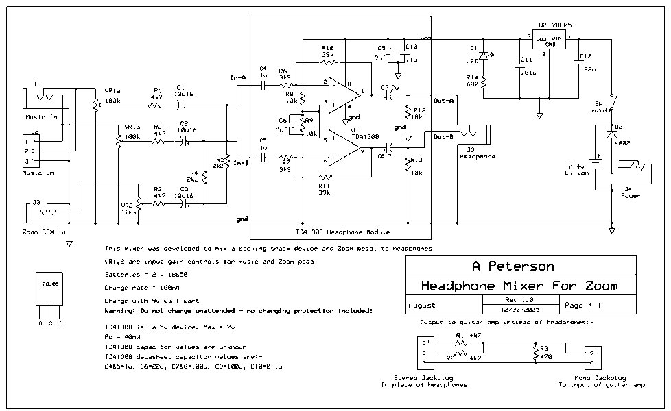
I am updating this article here, because one of the avid reader of our website, Mr. August Peterson, has sent me a superb modified circuit layout. Before, we learned about the LM386 guitar jammer but this is a new upgraded Headphone Mixer for Zoom guitar pedals using a cheap TDA1308 headphone module. This circuit solves a big problem for many hobbyists who want to play their electric guitar inside an effects pedal and listen on headphones while mixing a backing music track from mobile phone or MP3 player together.
How the Circuit Works
In this new layout, the core part is the TDA1308 integrated circuit, which is a very low voltage stereo headphone amplifier chip. The circuit has two inputs. First is for the backing music where we can see a smartly attached both an RCA socket and a 3.5mm mini stereo jack plug in parallel.
This is very good because you can directly plug any tape recorder, mobile phone, or MP3 player without searching for separate patch cables or converter pins. The second input is for the guitar effects pedal like the Zoom G3X.
The stereo music input has a dual gang potentiometer VR1a/VR1b to control the music volume. The guitar input (from the effects pedal) has a single gang potentiometer VR2 to control the guitar volume.
After the volume pots, the audio signals pass through mixing resistors 4k7 and 2k2 and DC blocking capacitors 10uF so that left and right channels get mixed properly before entering the input pins 2 and 5 of the TDA1308 chip.
The TDA1308 amplifier works as a non inverting stereo amplifier. The feedback resistors R10 and R11 are kept at 39k to set the sound gain.
Mr. August gave a very useful practical tip here. He says if you buy the cheap ready made TDA1308 modules from online markets, they usually give zero bass and sound very tiny. To fix this, you must solder extra 100uF 10V capacitors across the existing output capacitors C7 and C8. This will instantly increase the heavy bass response in your headphones.
Connecting to Guitar Amplifier instead of Headphones
If you do not want to use headphones and want to send the mixed output to a main guitar amplifier, there is a solution.
But please note, normal guitar amps do not have tweeters so music might sound a bit muddy but it is enough good for home practice. Because headphone output signals are very high power and low impedance, you cannot plug it directly to guitar amp input or it will blast loud distortion noise.
For this you have to make up a special attenuated patch cable as shown in the diagram. It uses two 4k7 series resistors and one 47 ohm shunt resistor to reduce the heavy stereo headphone signal into a safe mono instrument level signal for the amplifier.
Power Supply and Battery Warning
This TDA1308 is a 5V maximum device, so a 78L05 voltage regulator IC is used to give fixed 5V DC supply to the chip. For power source, we can see a 7.4V Lithium Ion battery pack.
But please read this warning very carefully. The diagram shows a direct 9V adapter with a 4002 diode for manual charging. You must carefully monitor the battery voltage with a meter and manually disconnect the supply when it reaches exactly 8.4V.
As we all know, manual charging of Lithium batteries is highly dangerous and can cause fire or damage if you forget to unplug.
So for all my inexperienced readers, I strictly recommend not to do manual charging. You should compulsorily add a proper 2S Lithium Ion battery charger module or BMS board to handle the charging automatically and safely.
Many thanks to Mr. August Peterson for sharing this wonderful and helpful design with our electronics community. If you have any doubts, please comment below.
Enhancing the Design with FET Preamp
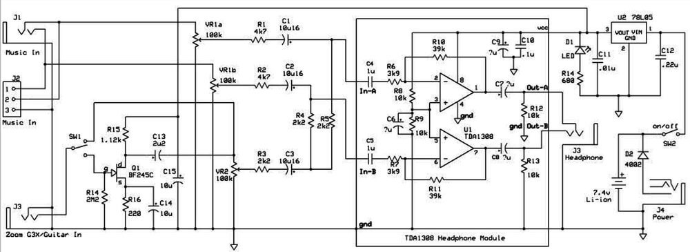
To include a greater audience (those without effect pedals) Mr. August has extended the Mixer to include a FET preamp so that an electric guitar can be plugged in and a switch activated to include the preamp in the chain. The preamp is powered from the 5v so the Drain voltage must be correct because of the limited headroom. The complete circuit diagram is shown below:
Explanation
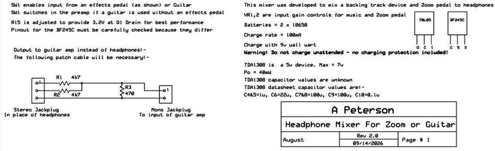
SW1 enables input from an effects pedal (as shown) or Guitar SW1 switches in the preamp if a guitar is used without an effects pedal R15 is adjusted to provide 3.2V at Q1 Drain for best performance Pinout for the BF245C must be carefully checked because they differ
Output to guitar amp instead of headphones:- The following patch cable will be necessary:-
Stereo Jackplug (In place of headphones) Mono Jackplug (To input of guitar amp) Diagram components: R1 4k7 R2 4k7 R3 470
This mixer was developed to mix a backing track device and Zoom pedal to headphones VR1,2 are input gain controls for music and Zoom pedal Batteries = 2 x 18650 Charge rate = 100mA Charge with 9v wall wart Warning: Do not charge unattended - no charging protection included!
TDA1308 is a 5v device. Max = 7v Po = 40mW TDA1308 capacitor values are unknown TDA1308 datasheet capacitor values are:- C4&5=1u, C6=22u, C7&8=100u, C9=100u, C10=0.1u
A Peterson Headphone Mixer For Zoom or Guitar August | Rev 2.0 09/14/2026 | Page # 1



Questions & Answers
Please check against the email schematic:-
VR1 a & b, VR2 : odd characters. R4 & R5 s/be 2k2.
P12, C11, C12, D2 odd characters.
Within the TDA1308:-
P6, C6, P7, P18, R11, P10, P12 ???
I can send new schematic if required
Thank you for your kind concerns. Yes, it seems it got messed up when I tried to make the schematic brighter, sharper and legible through an AI software, because original schematic was not clear enough, and could not be understood.
If you are sending the new schematic, please make sure the main schematic is bigger with little unused white spaces below the diagram, and the diagram is darker, sharper and all the component labels perfectly legible to the naked eye.
Thank you for notifying the issue, I will replace it with the new diagram once I get it from you.