The circuit explained here will provide LED indications and show if there's a possible fault in the wiring of your home AC Phase, Neutral, and Earth connections. The idea was requested by Mr. SS kopparthy.
Technical Specifications
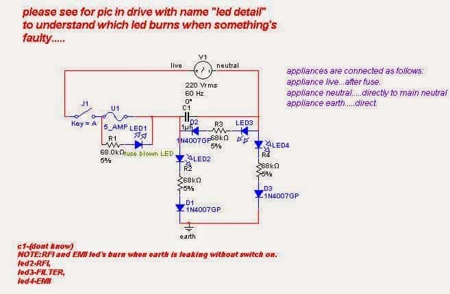
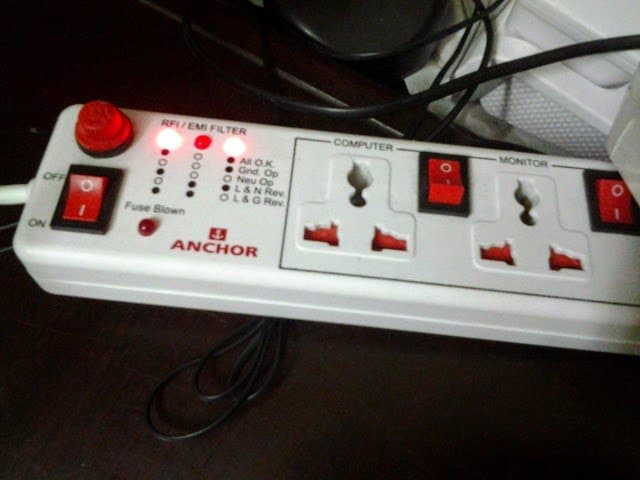
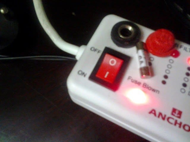
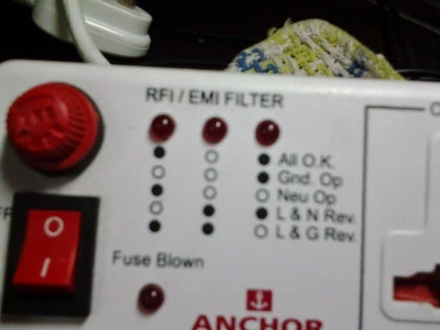
sir, very good morning. I thank you for your help. I further wanted you to consider a circuit whose pics are attached with links given.
This pcb would indicate me when earth is leaking(at that time the tester would burn when touched to earthing pin in 220v socket and will get a strong shock when touched by mistake.
Even the metal bodies of appliances give shock at that time.) by switching on the first two led's.if you look at the attached pics, you can see that the circuit has only a few resistors and diodes, and a black colored capacitor at back.
i also tried to draw the circuit diagram by seeing that pcb. the same pcb indicates the fuse blown condition.for circuit diagram and pictures of pcb, please see "
sir, i hope you understand the working of circuit and also hope you'll tell how its working to me also.......the purpose of writing this is that i would like you to help me by designing the circuit which has buzzer with led indication when something goes wrong. thank you very very very very very very very very much sir.........i cannot forget your help......
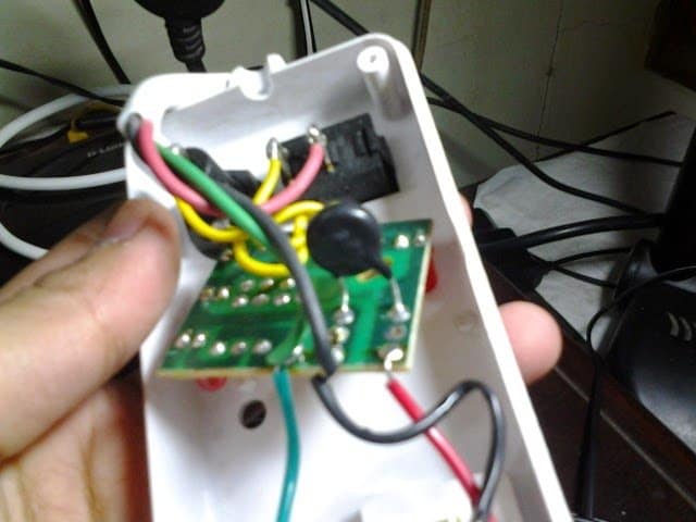
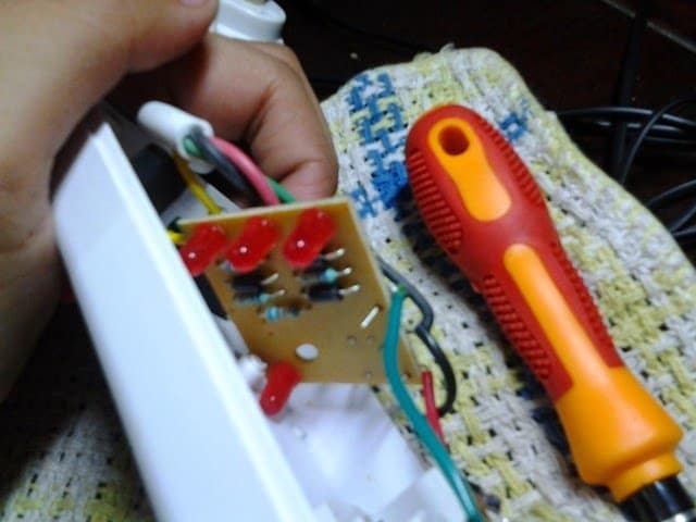
Using 3 LEDs for the Indications
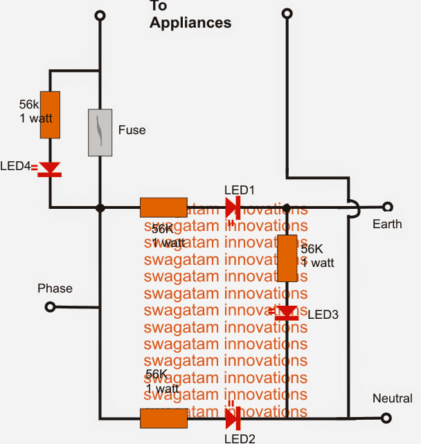
The above circuit can be much simplified and implemented using a just three LEDs and some resistors.
The circuit may be understood as follows.
The design of the proposed LIVE or phase, neutral, earth indicator circuit is rather simple.
As can be seen in the given diagram one LED is connected across the phase/neutral, another LED across phase/earth and a third one across neutral/earth.
Each LED has its own limiting resistor rated at 56K 1 watt.
The illuminations from the LEDs in response to the different L/N/E faulty conditions could be witnessed as given under:
LED1 and LED2 ON and LED3 OFF indicates a good overall situation wherein the phase, neutral and earth could be assumed to all wired correctly.
LED2 and LED3 ON and LED1 OFF indicates a wrong polarity of phase/neutral but earth and neutral may be assumed to be rightly configured.
All three LEDs ON indicates an open earth or neutral which may be diagnosed further. Since an open neutral is rare, the possibility of an open "earth" could be considered and investigated.
In addition to the phase, neutral, earth fault indications the circuit also employs a blown fuse indicator in the form of LED4 which simply lights up if the fuse is blown or open and a appliance hooked up.
Note tat the polarity of the LEDs are not crucial and could be used any way round.
Use of red LEDs is recommended, other types could show unusual responses.
The earth leakage sensor and buzzer circuit will be soon updated.
Simplified Schematic



Questions & Answers
hi Swagatam..
is there any chance to see a circuit of a transformless power inverter like 12/9amps to 220 v or 6v/4 amps to 15v ?
Hi Ahmad,
I'll start publishing them serially as soon as I crack how to design ferrite transformers as per the specific needs without using complex formulas, until then it would be difficult.
sir i build this and working fine but my collage sir ask me how i choose 56k resistor i need formula and explanation i mailed u also please reply as soon as possible thankx in advance
Vivek, it has been selected arbitrarily such that the LED produces good brightness and also the resistor stays cool…
although the actual formula is (220V – 3.3)/0.02….this gives around 11k but this value will need to be of 220 x 0.02 = 4.4 watts which can be bulky therefore 56k was chosen so that 1/4 watt could be used.
thankx a lot sir
What is the reason for C1?
It could be an MOV, not a capacitor
Hi Mr Swagatam Majumdar
In my country (Iran) there is no earth and I have circuit that need real phase and null entered , and
If the reverse were entered ،
The circuit does not work until the phase and neutral are correct.
Please guide me
Hi Hamid,
you can use a neon line tester to verify which side was the phase, and then plugin the device with correct polarity.
I hope I understood your requirement correctly…
Hi dear Swagatam
I have 3 questions about the first pic circuit :
1) In which amount of earth resistance, this instrument shows that earth is faulty?
2) If earth is disconnected, are the other tests (like L&N inverse) possible?
3) Can this instrument show that earth and ground are connected to each other, inside wall ?(if yes, which fault will be showed ?)
thank you for your help
Aslan, I cannot interpret the first circuit because it is not designed by me, and also because I feel it is not correctly designed.
Hi swagath sir, can you please send me the pcb schematic for the circuit. I was looking for it for quite a long time. And is there any problem for the first given circuit? I have one similar to that but burnt out some way .All the three LEDs and 2 resistors are burnt.
Hi Binoj, sorry I do not have a PCB design for this project. use 1 watt wirewound resistors, they won’t burn
Hi Swagatam,
I am working on EMI/RFI filter and Surge suppression circuit for Extension board (230-250 VAC,50 Hz supply) and looking for standard circuit for the same. Can you please send me the optimized PCB circuit and schematic for EMI/RFI filter and Surge suppression circuit?
Regards,
Umesh
Hi Umesh, you can try the following circuit:
Thank Swagatam for your prompt response. Is it possible to include indicator LED’s for Phase,Neutral and Earth. I am having modified circuit but don’t know if it is right or wrong? I am not able to share image of circuit with you in comment box. Is any other way of sharing circuit?
Regards,
Umesh
Umesh, for LED connections you may have to implement the second circuit which is explained in the above article. You can also try your modified design by connecting the L, N. E wires across the relevant lines. You can share the image through Google drive.
Hi Swagatam,
Again Thanks for your response. Based on your circuit details and combining it with LED indications I prepared modified circuit. Please check on following google drive link for comments and let me know if changes required.
https://drive.google.com/file/d/1KEQghUqLpgeGl9pI4kFfMxBHs85t_orP/view?usp=sharing
Regards,
Umesh
Hi Umesh, please change the link to sharing mode so that it becomes accessible to me.
Hi Swagatam,
Please access following link.
https://drive.google.com/file/d/1KEQghUqLpgeGl9pI4kFfMxBHs85t_orP/view?usp=sharing
Regards,
Umesh
Hi Umesh, the LEDs should be on the switch side according to me, as shown below.
But the RFI section is not as per my design so I cannot comment on that.
Can we get a PCB for assembling the Phase-Earth-Neutral fault indicator circuit?